EasyManua.ls Logo

Trane Mitsubishi Electric CITY MULTI TPLFYP036EM140B User Manual

Trane Mitsubishi Electric CITY MULTI TPLFYP036EM140B
44 pages
To Next Page IconTo Next Page
Page #1 background imageLoading...
Page #1 background image
TECHNICAL & SERVICE MANUAL
Indoor unit
[Model Name]
CONTENTS
1. SAFETY PRECAUTION
..........................
2
2. PARTS NAMES AND FUNCTIONS
........
4
3. SPECIFICATIONS
.................................
12
4. 4-WAY AIRFLOW SYSTEM
..................
18
5. OUTLINES AND DIMENSIONS
............
21
6. WIRING DIAGRAM
...............................
22
7.
REFRIGERANT SYSTEM DIAGRAM
......
23
8. MICROPROCESSOR CONTROL
.........
24
9. TROUBLESHOOTING
..........................
31
10. DISASSEMBLY PROCEDURE
...........
39
INDOOR UNIT
PARTS CATALOG (OCBT746)
R410A
August 2020
No. OCHT746
REVISED EDITION-A
Grille model
[Model Name]
TLP-41EAEU
WIRED REMOTE
CONTROLLER
(Option)
IR WIRELESS REMOTE
CONTROLLER
(Option)
ON/OFF TEMP
MENU
ON
OFF
RETURN
SELECT
HOLD
Model name
indication for
MAIN UNIT
Model name
indication for GRILLE
TPLFYP006EM140B
TPLFYP008EM140B
TPLFYP012EM140B
TPLFYP015EM140B
TPLFYP018EM141B
TPLFYP024EM140B
TPLFYP030EM140B
TPLFYP036EM140B
TPLFYP048EM140B
INDOOR UNIT FOR VRF SYSTEM
Revision:
5.OUTLINES AND
DIMENSIONS has been
revised.
Some descriptions
have been modified
in
REVISED EDITION-A
.
OCHT746 is void.
Question and Answer IconNeed help?

Do you have a question about the Trane Mitsubishi Electric CITY MULTI TPLFYP036EM140B and is the answer not in the manual?

Trane Mitsubishi Electric CITY MULTI TPLFYP036EM140B Specifications

General IconGeneral
SEERUp to 20.5
RefrigerantR410A
Cooling Capacity (BTU/h)36000
Power Supply208-230V, 60Hz
Outdoor Unit Dimensions (HxWxD)845x950x340 mm

Summary

Safety and Handling Precautions

Refrigerant Handling and Tool Safety

Safety guidelines for handling refrigerants, tools, and precautions for R410A.

Service Cautions and Procedures

Important cautions to follow during service operations and refrigerant charging.

Unit Components, Controls, and Specifications

Indoor Unit Components and Controls

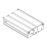
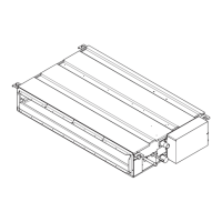
Identifies indoor unit parts and explains wired remote controller interface and functions.

Remote Controller Menu and Display

Overview of the remote controller's menu system, settings, and display icons.

Detailed Technical Specifications

Comprehensive technical data including capacity, power, dimensions, and performance.

Installation, Diagrams, and Operation

Installation and Airflow Configuration

Guides on airflow setup, ducting, and wiring connections for installation.

System Diagrams and Operation Modes

Illustrates refrigerant flow and explains control logic for various operation modes.

Troubleshooting and Disassembly

Troubleshooting Component Checks

Procedures for checking various parts for faults using diagnostic methods.

DIP Switch and Controller Settings

Details DIP switch functions and advanced controller settings for troubleshooting.

Component Disassembly Procedures

Step-by-step guide for removing major components like fans, motors, and heat exchangers.

Related product manuals