EasyManua.ls Logo

Trane Mitsubishi Electric NTXMMX24A132A Series User Manual

Trane Mitsubishi Electric NTXMMX24A132A Series
24 pages
To Next Page IconTo Next Page
Page #1 background imageLoading...
Page #1 background image
Split-type Air-Conditioner
NTXMMX24A132A
NTXMMX30A132A
NTXMMX36A142A
Installation Manual
For INSTALLER
This manual only describes the installation of outdoor unit.
When installing the indoor unit, refer to the installation manual of indoor unit.
Any structural alterations necessary for installation must comply with local build-
ing code requirements.
Notice d’installation
Destinée à l
INSTALLATEUR
Cette notice ne décrit que l’installation de l’appareil extérieur.
Lors de l’installation de l’appareil intérieur, consultez la notice d’installation de cet
appareil.
Toute altération structurelle requise pour l’installation doit être conforme aux exi-
gences du code du bâtiment local.
Manual de instalación
Para el INSTALADOR
En este manual sólo se describe la instalación de la unidad exterior.
Para instalar la unidad interior, consulte el manual de instalación de dicha uni-
dad.
Cualquiermodicaciónestructuralnecesariaparallevaracabolainstalaciónde-
berácumplirlasnormasdeedicaciónlocales.
Español
Français
English
WG79A765H01_01En.indd 1 2018/08/03 9:41:29
Question and Answer IconNeed help?

Do you have a question about the Trane Mitsubishi Electric NTXMMX24A132A Series and is the answer not in the manual?

Trane Mitsubishi Electric NTXMMX24A132A Series Specifications

General IconGeneral
BrandTrane
ModelMitsubishi Electric NTXMMX24A132A Series
CategoryAir Conditioner
LanguageEnglish

Summary

1. BEFORE INSTALLATION

1-1. SAFETY PRECAUTIONS

Crucial safety warnings and cautions must be observed before installing the air conditioner.

1-2. SPECIFICATIONS

Details technical specifications including power supply, pipe length, and refrigerant adjustments.

1-3. OPTIONAL DIFFERENT-DIAMETER JOINTS

Guidance on using optional joints when outdoor unit port size differs from connection pipe size.

1-4. INSTALLATION LOCATION SELECTION

Provides criteria and considerations for choosing an appropriate installation site for the outdoor unit.

FREE SPACE REQUIREMENTS

Specifies required clearances around the outdoor unit based on surrounding obstacles.

1-5. INSTALLATION DIAGRAM

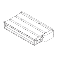
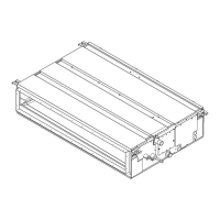
Illustrates the installation layout and dimensions for the outdoor unit.

2. OUTDOOR UNIT INSTALLATION

2-1. INSTALLING THE UNIT

Instructions for securely mounting the outdoor unit, including foundation and anchoring.

2-2. CONNECTING WIRES

Detailed steps for electrical wiring connections, including power supply and ground wires.

3. FLARING WORK AND PIPE CONNECTION

3-1. FLARING WORK

Procedure for correctly flaring copper pipes for refrigerant line connections.

3-2. PIPE CONNECTION

Steps for connecting refrigerant pipes to the outdoor unit, including lubrication and tightening.

3-3. INSULATION AND TAPING

Guidelines for insulating and taping refrigerant pipes to prevent condensation and burns/frostbite.

4. PURGING PROCEDURES, LEAK TEST, AND TEST RUN

4-1. PURGING PROCEDURES AND LEAK TEST

Steps for evacuating refrigerant lines and performing leak detection after installation.

4-2. GAS CHARGE

Procedure for charging the system with the correct amount of refrigerant for cooling operation.

4-3. TEST RUN

Instructions for performing a test run to verify proper operation and detect wiring/piping issues.

4-4. EXPLANATION TO THE USER

Guidance on explaining the unit's operation and maintenance to the end-user.

5. PUMPING DOWN

Related product manuals