19
18-HD82D1-1B-EN
XR724 INSTALLER’S GUIDE
2
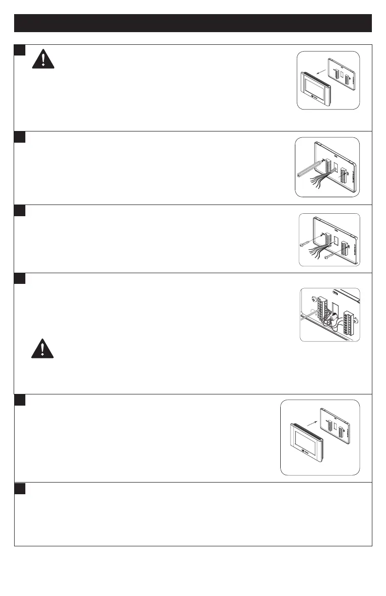
Mark two mounting holes using new wall plate.
• Pull wires through hole in center of wall plate.
• Locate the new wall plate over existing opening.
• Mark two holes with pencil.
• Use a level to verify that the two hole locations are level.
• Correct hole locations as needed.
4
Attach all wires securely to the new Comfort Control.
(See the Field Wiring Diagrams on the following pages.)
Note: A wire must be connected to “C” to power the Comfort Control.
• Use the information from the Field Wiring Diagrams to match the
wires to the correct terminals.
• Use 1/8” blade screwdriver to secure wires in terminals.
CAUTION: EQUIPMENT DAMAGE HAZARD
Improper wiring can lead to equipment damage. Use the eld wiring diagrams to ensure the Comfort Control is wired properly. After
wires are secure, bare wires MUST NOT touch each other. See the Field
Connection Wiring Diagrams on the following pages for specic system applications.
3
Install new wall plate.
• Pull wires through hole in center of wall plate.
• Locate the new wall plate over existing opening.
• Attach wall plate to wall using two screws provided. Do not overtighten.
AUX/C
J2 AUX NC
C
R
W1
W2
O/B
G
BK
J2
J1
RS
RS
ODT
ODT
AUX NO
Y1
Y2 J1
AUX/C
J2 AUX NC
C
R
W1
W2
O/B
G
BK
J2
J1
RS
RS
ODT
ODT
AUX NO
Y1
Y2 J1
AUX/C
J2 AUX NC
C
R
W1
W2
O/B
G
BK
J2
J1
RS
RS
ODT
ODT
AUX NO
Y1
Y2 J1
6
Turn power to heating and cooling system back on.
The Comfort Control display should turn on and begin displaying information.
Proceed to Installer’s Setup to congure system
settings.
5
Attach the Comfort Control face to the wall plate.
a. Carefully align the face plate to the wall plate while aligning pins
into wire terminals.
b. Once Comfort Control face is properly aligned, apply pressure at
top and bottom of
Comfort Control face until it is secure.
1
CAUTION: Before proceeding with installation, verify system power has been removed.
Separate the face of the new Comfort Control from the wall plate.
Î NOTE: It is not recommended that this WiFi Comfort Control be mounted onto
metal structures. Metal may adversely affect the radio frequency (RF) communication
between the Comfort Control and the WiFi network .
CAUTION: ELECTRICAL HAZARD
AUX/C
J2 AUX NC
C
R
W1
W2
O/B
G
BK
J2
J1
RS
RS
ODT
ODT
AUX NO
Y1
Y2 J1
AUX/C
J2 AUX NC
C
R
W1
W2
O/B
G
BK
J2
J1
RS
RS
ODT
ODT
AUX NO
Y1
Y2 J1
 Loading...