15
10.WIRING DIAGRAM
1. To avoid getting exposed to the electrical shock, please connect the ground wire on the air handler with help of the
ground lug provided. The main power plug on the air handler unit should be tied with the ground wire to provide enough
strain relief. Please do not change the power wires or the ground connection unless required.
2. The power socket is used only on the air handler units.
3. Do not pull hard or apply tension on the power wires since the main connection to the unit might damage and fail.
4. When connecting the air handler unit with the ground, please comply with the local codes.
5. If necessary, use the power fuse or the circuit breaker as per the ampacity requirements.
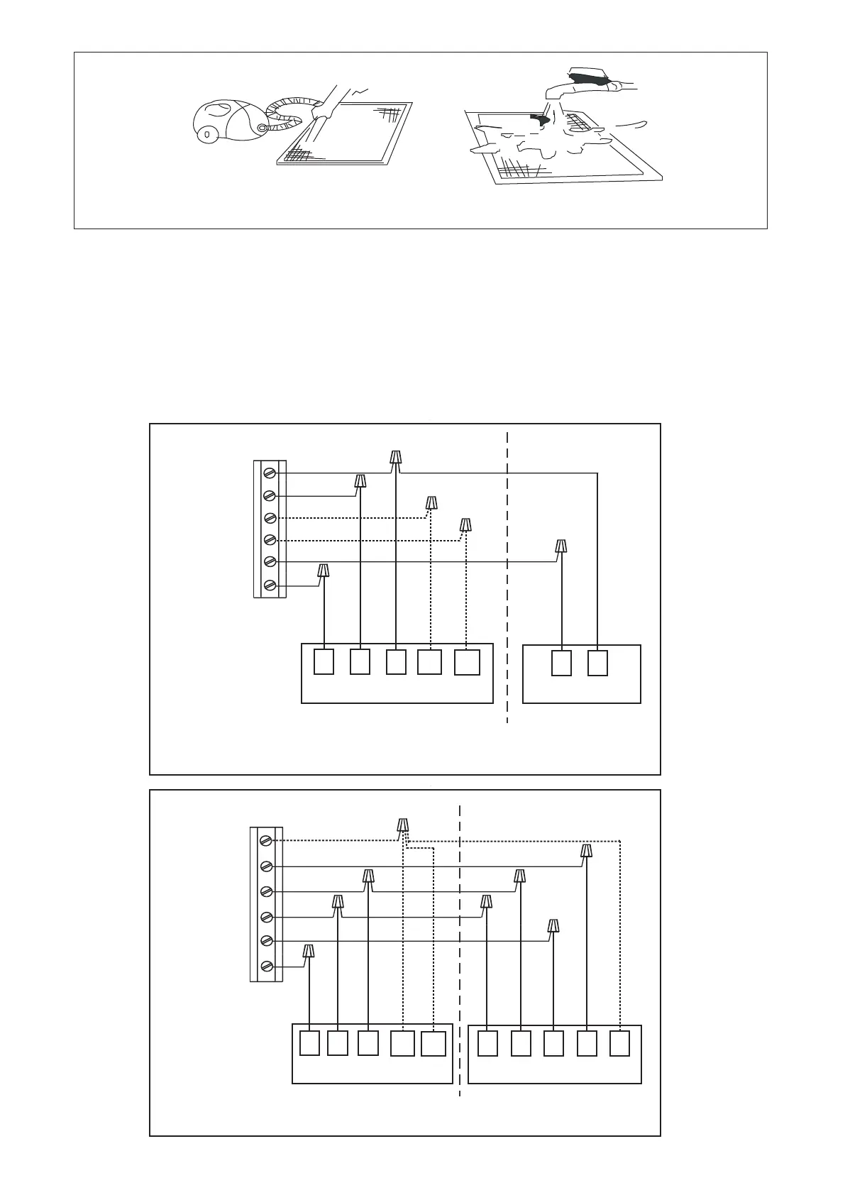
Fig.14 CONTROL WIRING FOR AC SYSTEMS
Fig.15 CONTROL WIRING FOR HP SYSTEMS
RED
GREEN
24RC
G Fan
Y1 Comp
W1/B
THERMOSTAT
INDOOR UNIT OUTDOOR UNIT
G R C Y C
BLACK
YELLOW
BLACK
RED
GREEN
W2
G Fan
Y1 Comp
W1/B
THERMOSTAT
INDOOR UNIT OUTDOOR UNIT
G R C
C B
BLACK
YELLOW
BLACK
W1
R
Y D
24C
24RC
RED
BLUE
PURPLE
W1
W2
WHITE
24C
W2
W2
WHITE
BLACK/WHITE
BLACK/WHITE
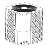
Fig.13 AIR FILTER CLEAN
 Loading...