07
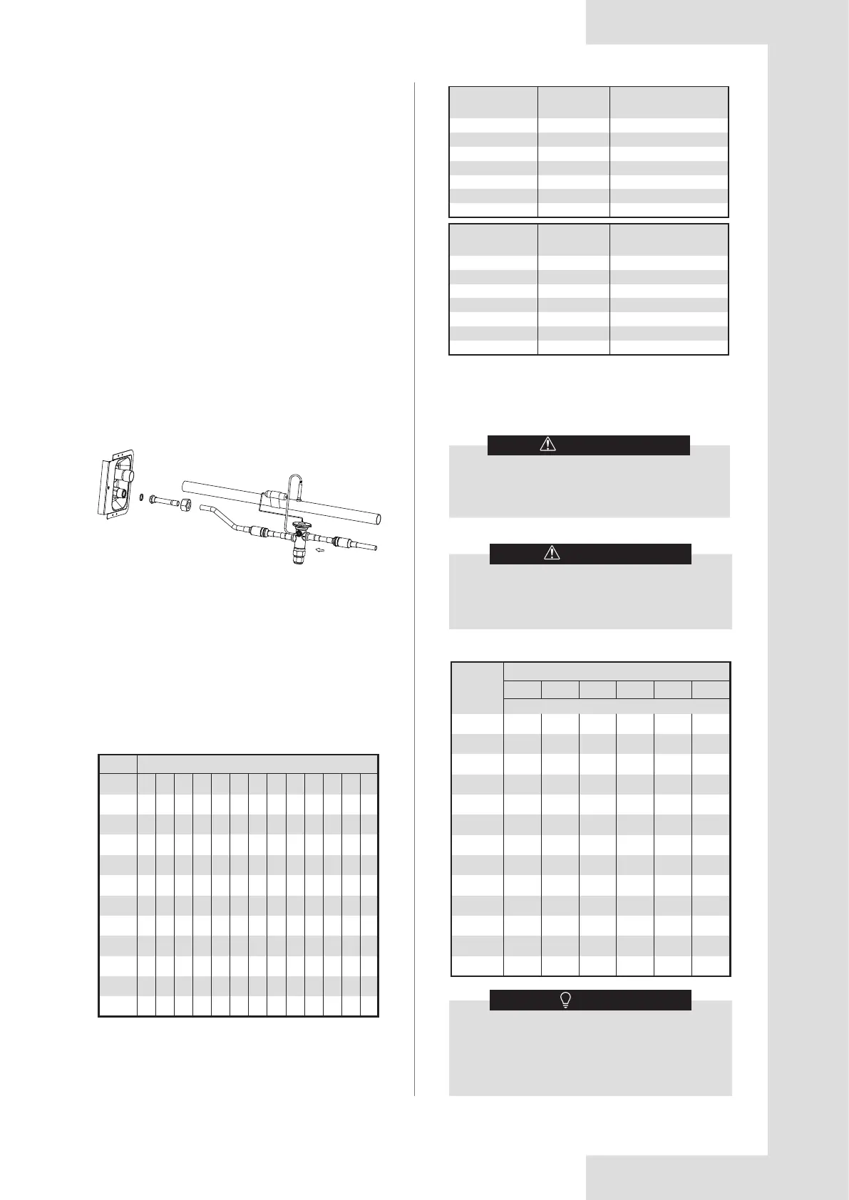
6.2 Optional TXV Kit Installation
WARNING
Failure to install the proper piston can lead to
poor system performance and possible compres-
sor damage.
1.Use a wrench to loosen the nut and remove the
sealing flange and sealing gasket.
2.Take out the connecting pipe from accessory package
and braze the connecting pipe onto the refrigeration-out
pipe.
3.Install the sealing washers, TXV and flange connec-
tion tube.
4.Use a wrench fasten nut and connecting pipe.
(18±2N·m).
5.Connect TXV equalizer pipe to the port on the
connecting pipe.
6.Fix bulbs on the connecting pipe using use accessory
in TXV kit.
Fig 6-2
* The ship-with literature bag will contain additional
R-410A pistons for most applications.
* Contact your local parts center to order the appropriate
piston if it is not included with the literature.
Reference TXV kit literature for installation instructions.
A TXV may be required to achieve minimum efficiency
ratings or for long refrigerant line set applications.
Reference AHRI for system combination ratings.
Reference Table 6-2 to charge the system by superheat
when using piston.
Reference the outdoor unit installation guide to charge
the system when using a TXV.
Table 6-1 Factory installed piston size for each coil
model. Additional piston sizes are provided in the
ship-with literature bag as necessary.
Table 6-3 Piston superheat charging chart
Piston/orifice sizes
J4MX
Model
CA003E
CB004E
CC005E
CB006E
CC007E
CD008E
CB016E
CC017E
CD018E
CC009E
CD010E
50 52
X
X
X
X
56 58
X
X
X
X
60
X
X
X
X
X
X
64
X*
X*
X*
X
X
X
X
X
68 70
X
X
X
X
X
X
X
X
X
73 75
X*
X*
X*
X
X
X
X
X
80
X
X
83
X*
X*
X*
X
X
90
X*
X*
* means that this piston is pre-installed
CAUTION
An improperly charged system will likely cause
loss in system performance and may damage
the compressor.
Indoor Temperature(°F) Dry Bulb/Wet Bulb
Outdoor
temp(°F)
95/79 90/75 85/71 80/67 75/63 70/58
Superheat
23
24
26
27
29
30
35
34
35
37
38
40
41
16
17
19
21
23
25
26
28
30
32
34
36
37
7
9
11
13
16
18
20
22
24
26
29
31
33
5
5
5
7
9
12
14
17
19
21
24
27
29
5
5
5
5
5
5
8
11
13
16
19
22
25
5
5
5
5
5
5
5
5
6
10
13
17
21
115
110
105
100
95
90
85
80
75
70
65
60
55
Chart is based on 400CFM/Ton indoor airflow
and 50% relative humidity. If indoor relative
humidity is above 70% or below 20%, use indoor
wet bulb temperature only.
Airflow range is 375 to 425 CFM/Ton
NOTE
Table 6.2. Use chart below when matching coil with
outdoor unit. Addition piston sizes are provided in the
ship-with literature bag as necessary.
Outdoor Unit
Capacity (Tons)
Piston Size*
(R410a)
Piston Kit
1.5
2
2.5
3
3.5
4
5
52
58
63
70
75
83
90
MAYORIACHP0052B
MAYORIACHP0058B
MAYORIACHP0063B
MAYORIACHP0070B
MAYORIACHP0075B
MAYORIACHP0083B
MAYORIACHP0090B
Outdoor Unit
Capacity (Tons)
Piston Size*
(R22)
Piston Kit
1.5
2
2.5
3
3.5
4
5
52
58
65
72
78
88
96
MAYORIACHP0052B
MAYORIACHP0058B
MAYORIACHP0065A
MAYORIACHP0072B
MAYORIACHP0078B
MAYORIACHP0088B
MAYORIACHP0096B
*Piston size needed for system combination may not be
pre-installed.
See Table 6.1 for pre-installed size.