ACC-SVN240A-EN 11
Installation
1. Turn the main power disconnect switch OFF.
2. Remove the filter access panel.
3. Remove the rear access panel directly above the horizontal supply duct cover. The sensor tube
will hang from the fan divider wall with service access to the fan wall from both the rear access
panel as well as access through the supply duct opening. Refer to Figure 14.
4. Remove the supply air duct cover on the rear side of the unit.
5. Install the sensing tube through the fan wall hole as shown in Figure 10.
Table 1. Gap analysis chart – B.0 and C.0 cabinet
Heater Type HZ Gap Low DF Gap Low HZ Gap Med DF Gap Med HZ Gap High DF Gap High
TLSP; GAS heat, B0 Cabinet, 3x3, L2 3/4 inch 3/4 inch
TLSP; GAS heat, B0 Cabinet, 3x4, L2 3/4 inch 3/4 inch 3/4 inch 3/4 inch
TLSP; GAS heat, B0 Cabinet, 4x5, L2 3/4 inch 3/4 inch 3/4 inch Tight 3/4 inch Tight
TLSP; GAS heat, B0 Cabinet, 6x7, L2 3/4 inch Tight 3/4 inch Tight
TLSP; GAS heat, C0 Cabinet, 4x5, L3 1/8 inch 1/8 inch 1/8 inch 3/4 inch
TLSP; GAS heat, C0 Cabinet, 6x7, L3 1/8 inch 1/8 inch
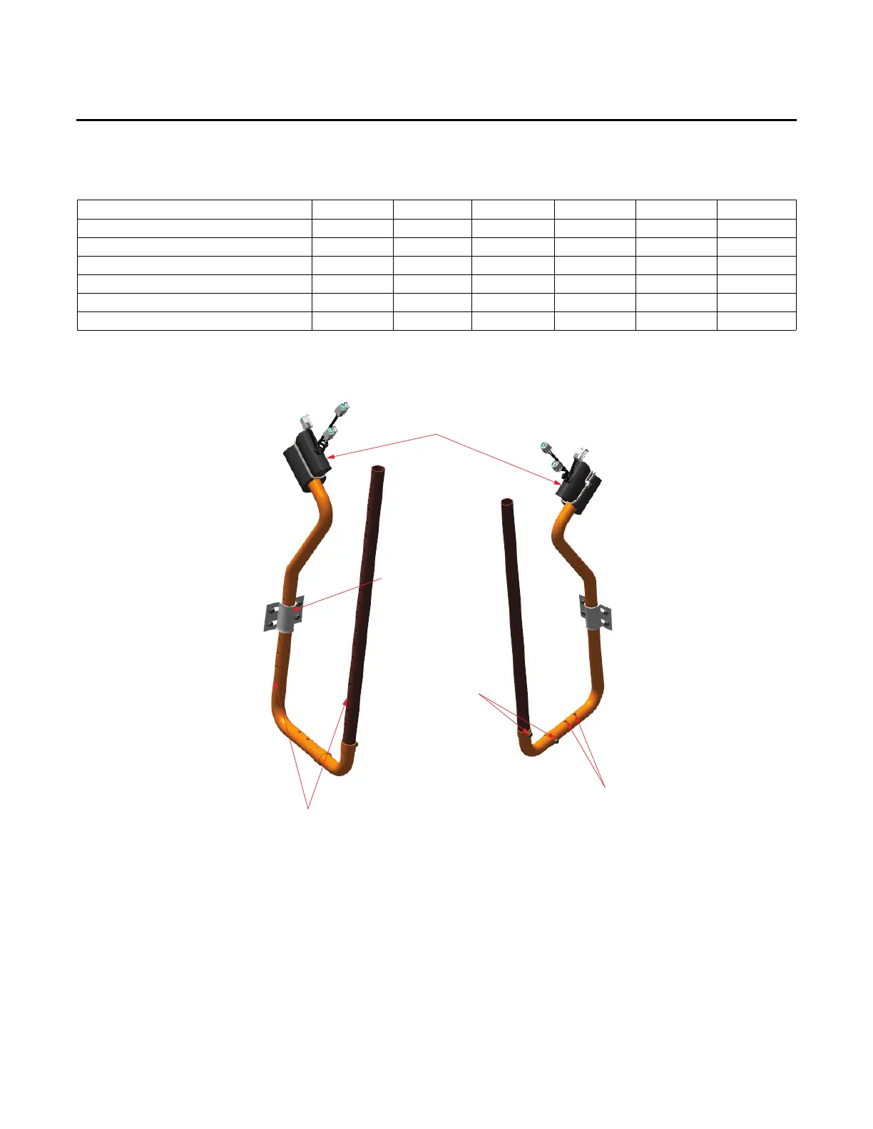
Figure 9. For model: D cabinet (digit 39 = D) horizontal installation
Temperature sensing assembly
with insulation
Secure clamp with
screws into fan wall
Secure three tubes
with screws
Tubing holes face towards front of unit
(opposite horizontal supply duct)
Tubing holes face vertically
upwards toward fan
 Loading...