4
PKGP-SVX010B-EN
Model Number Description . . . . . . . . . . . . . . . . . . . 6
General Information . . . . . . . . . . . . . . . . . . . . . . . . . 8
Unit Inspection . . . . . . . . . . . . . . . . . . . . . . . . . . . . 8
Exterior Inspection . . . . . . . . . . . . . . . . . . . . . 8
Inspection for Concealed Damage. . . . . . . . 8
Unit Storage . . . . . . . . . . . . . . . . . . . . . . . . . . . . . . 8
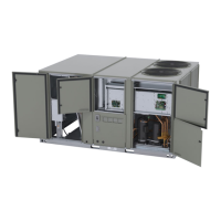
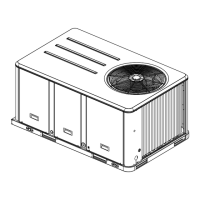
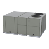
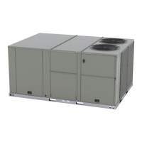
Unit Description . . . . . . . . . . . . . . . . . . . . . . . . . . . 8
Door Handles . . . . . . . . . . . . . . . . . . . . . . . . . . . . . 8
Unit Nameplate. . . . . . . . . . . . . . . . . . . . . . . . . . . . 8
Compressor Nameplate . . . . . . . . . . . . . . . . . . . . 9
LonTalk Communication Interface
(Optional). . . . . . . . . . . . . . . . . . . . . . . . . . . . . . . . . 9
BACnet Communications Interface
(Optional). . . . . . . . . . . . . . . . . . . . . . . . . . . . . . . . . 9
System Input Devices and Functions . . . . . . . . . 9
Supply Fan Failure . . . . . . . . . . . . . . . . . . . . . 9
Clogged Filter Switch (Optional). . . . . . . . . . 9
Condensate Drain Pan Overflow
Switch . . . . . . . . . . . . . . . . . . . . . . . . . . . . . . . . 9
Compressor Disable (CPR1/2) . . . . . . . . . . . 9
Low Pressure Control . . . . . . . . . . . . . . . . . . . . . . 9
High Pressure Control . . . . . . . . . . . . . . . . . . . . . 10
Zone Sensors . . . . . . . . . . . . . . . . . . . . . . . . . . . . 10
Manual Changeover
(BAYSENS106*) . . . . . . . . . . . . . . . . . . . . . . 10
Manual/Automatic Changeover
(BAYSENS108*) . . . . . . . . . . . . . . . . . . . . . . 10
Wall Mounted Relative Humidity
Sensor (BAYSENS036*) . . . . . . . . . . . . . . . 10
Duct Mounted Relative Humidity
Sensor (BAYSENS037*) . . . . . . . . . . . . . . . 10
Integrated Comfort System
(BAYSENS073*) . . . . . . . . . . . . . . . . . . . . . . 10
Integrated Comfort System
(BAYSENS074*) . . . . . . . . . . . . . . . . . . . . . . 10
Remote Zone Sensor
(BAYSENS016*) . . . . . . . . . . . . . . . . . . . . . . 10
Remote Zone Sensor
(BAYSENS077*) . . . . . . . . . . . . . . . . . . . . . . 10
Thermostat. . . . . . . . . . . . . . . . . . . . . . . . . . . 10
High Temperature Sensor
(FIAHTST001*) . . . . . . . . . . . . . . . . . . . . . . . 10
Digital Display Zone Sensor
(BAYSENS135*) . . . . . . . . . . . . . . . . . . . . . . 10
Touch Screen Programmable Zone
Sensor (BAYSENS800) . . . . . . . . . . . . . . . . 11
Evaporator Frost Control. . . . . . . . . . . . . . . . . . . 11
Discharge Line Temp Switch (DLTS) . . . . . . . . 11
Smoke Detector Sensor (Optional) . . . . . . . . . . 11
Phase Monitor . . . . . . . . . . . . . . . . . . . . . . . . . . . 11
Pre-Installation . . . . . . . . . . . . . . . . . . . . . . . . . . . . . 12
Precautionary Measures. . . . . . . . . . . . . . . . . . . 12
First Aid Measures . . . . . . . . . . . . . . . . . . . . . . . . 12
Dimensional Data. . . . . . . . . . . . . . . . . . . . . . . . . . . 13
Clearances . . . . . . . . . . . . . . . . . . . . . . . . . . . . . . 17
Weights . . . . . . . . . . . . . . . . . . . . . . . . . . . . . . . . . 18
Lifting and Rigging . . . . . . . . . . . . . . . . . . . . . . . . 19
Installation . . . . . . . . . . . . . . . . . . . . . . . . . . . . . . . . . 20
Horizontal Units . . . . . . . . . . . . . . . . . . . . . . . . . . 20
Ductwork . . . . . . . . . . . . . . . . . . . . . . . . . . . . . . . . 20
Roof Curb . . . . . . . . . . . . . . . . . . . . . . . . . . . . . . . 21
Downflow . . . . . . . . . . . . . . . . . . . . . . . . . . . . 21
Rigging . . . . . . . . . . . . . . . . . . . . . . . . . . . . . . 21
General Unit Requirements . . . . . . . . . . . . . . . . 22
Factory Installed Economizer . . . . . . . . . . . 22
External Vent Hood Installation. . . . . . . . . . 22
Temperature Limit Switch Usage for
Gas Heat Units . . . . . . . . . . . . . . . . . . . . . . . 23
TCO1 Instructions . . . . . . . . . . . . . . . . . . . . . . . . 23
Return Air Smoke Detector. . . . . . . . . . . . . . . . . 24
Air-Fi® Wireless Communication
Interface. . . . . . . . . . . . . . . . . . . . . . . . . . . . . . . . . 25
Main Electrical Power Requirements . . . . . . . . 26
Electric Heat Requirements . . . . . . . . . . . . 26
Low Voltage Wiring. . . . . . . . . . . . . . . . . . . . 26
Through-the-Base Gas Installation . . . . . . . . . . 26
Requirements of Gas Heat . . . . . . . . . . . . . . . . . 27
Condensate Drain Configuration . . . . . . . . . . . . 27
Drain Pan Removal (Units with
Condensate Overflow Switch
Option) . . . . . . . . . . . . . . . . . . . . . . . . . . . . . . 28
Filter Installation . . . . . . . . . . . . . . . . . . . . . . . . . . 28
Field Installed Power Wiring. . . . . . . . . . . . . . . . 28
Main Unit Power . . . . . . . . . . . . . . . . . . . . . . . . . . 28
Standard Wiring . . . . . . . . . . . . . . . . . . . . . . 28
Optional TBUE Wiring (Through-the-
Base Electrical Option) . . . . . . . . . . . . . . . . 29
Field-Installed Control Wiring . . . . . . . . . . . 29
Control Power Transformer. . . . . . . . . . . . . 29
Controls using 24 Vac . . . . . . . . . . . . . . . . . 29
Controls using DC Analog Input/
Outputs (Standard Low Voltage Multi
conductor Wire). . . . . . . . . . . . . . . . . . . . . . . 31
DC Conductors . . . . . . . . . . . . . . . . . . . . . . . 31
Space Temperature Averaging . . . . . . . . . . . . . 31
Table of Contents