W
washingtonjoeAug 10, 2025
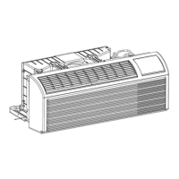
What to do if my Trane ProSpace PTHG1502HAA Heat Pump is losing refrigerant or has a sensor issue?
- WWillie GrantAug 10, 2025
If your Trane Heat Pump is losing refrigerant or has a sensor issue: * Inspect the unit, especially the refrigerant system, for leaks or visible damage. * Observe the refrigerant circuit temperatures. * Check that the tube temperature sensor on the condenser coil is snug in its sleeve. * Ensure the ambient temperature sensor in front of the evaporator coil is secure and not touching the coil. * Verify that the inner and outer tube temperature sensors are correctly plugged into the board inside the compartment below the on-board mounted controls and are not reversed.