SS-SVX09A-EN 33
Installation
Split System Component Number Definitions
(1)Interconnecting Suction Line Tubing
(2)Suction Line Filter
(3)Shutoff Valves - Manual ball valves
(4)Interconnecting Liquid Line Tubing. If risers exceed 10 feet, Trane must review the application
(5)Shutoff valves - Manual ball valves
(6)Access Ports
(7)Liquid Line Filter Drier
(8)Liquid Line Solenoid Valve
(9)Moisture and Liquid Indicator
(10)FrostatTM (Required for coil freeze protection)
(11)Expansion Valve (One Expansion Valve for each Coil Distributor)
(12)Evaporator Coil
Table 6. Solenoid Valve & Sight Glass w/Moisture Indicator
Capacity
Solenoid Valve
(Sporlan)
Solenoid Valve Coil
(Sporlan)
Sight Glass with
Moisture Indicator
(Sporlan)
20 Ton E19S250 MKC-2 @ 120V SA-15S
25 Ton E19S270 MKC-2 @ 120V SA-17S
30 Ton E19S270 MKC-2 @ 120V SA-17S
40 Ton E19S250 MKC-2 @ 120V SA-15S
50 Ton E19S270 MKC-2 @ 120V SA-17S
60 Ton E19S270 MKC-2 @ 120V SA-17S
Note: Use specific parts listed or equivalent. (Per Circuit)
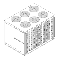
Figure 18. Typical Placement of Split System piping Components