EasyManua.ls Logo

Trane RAUC-C50 - User Manual

Trane RAUC-C50
112 pages
To Next Page IconTo Next Page
Loading...
June 2008
SS-SVX09A-EN
Installation
Operation
Maintenance
Remote Split System Units
Air Cooled Condensing Units and EVP Chillers
Models
“V” and Later Design Sequence
RAUC-C20 RAUC-C40
RAUC-C25 RAUC-C50
RAUC-C30 RAUC-C60

Table of Contents

Question and Answer IconNeed help?

Do you have a question about the Trane RAUC-C50 and is the answer not in the manual?

Trane RAUC-C50 Specifications

General IconGeneral
Cooling Capacity50 tons
Refrigerant TypeR-410A
Voltage208/230 V
Phase1
Sound Level (Outdoor Unit)76 dB

Summary

Warnings, Cautions and Notices

Important Environmental Concerns!

Discusses the impact of man-made chemicals on the ozone layer.

Responsible Refrigerant Practices!

Emphasizes certified technicians and following refrigerant laws.

Grounding Required!

Highlights the necessity of proper electrical grounding for safety.

Overview of Manual

General Information

Model Number Description

Details the alphanumeric code used to identify unit type, capacity, and options.

Installation

Unit Inspection

Checks to perform upon unit arrival for damage and completeness.

Unit Clearances

Specifies minimum distances for operation, service, and efficiency.

EVP Chiller Considerations

Details indoor installation requirements for EVP chillers.

Unit Dimensions & Weight Information

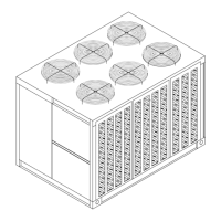
Provides dimensional data and weight specifications for units.

Foundation

Discusses requirements for unit support and anchoring.

Rigging

Rigging and Center-of-Gravity Data

Illustrates rigging procedures and provides center-of-gravity information.

Unit Isolation

Neoprene Isolators

Details the installation procedure for neoprene isolators.

Spring Isolators

Provides installation procedures for spring isolators.

Leveling the Unit

Describes how to level the unit using isolators and shims.

Shipping Fasteners

Compressor Shipping Hardware

Explains how to remove shipping hardware from compressors.

Two Manifolded Compressors

Details securing and removing shipping braces for manifolded compressors.

General Unit Requirements

Refrigerant Piping Requirements

EVP Chilled Water Piping Requirements

Main Electrical Power Requirements

Field Installed Control Wiring Requirements

115 Volt Control Wiring (All Units)

Covers wiring for components using 115 VAC power.

”No Controls” Units

Specifies field-provided controller requirements for 'No Controls' units.

“EVP” Chiller Units

Details wiring for EVP chiller remote panel connections.

Low Voltage Wiring (AC & DC)

Variable Air Volume (VAV) Units

Wiring instructions for VAV unit control components.

EVP Chiller Units

Wiring instructions for EVP chiller unit controls.

Constant Volume Units

Wiring instructions for Constant Volume unit controls.

Refrigerant Line Components

Suction And Liquid Line Filter;Filter Drier (Field Supplied)

Describes installation of suction and liquid line filters/driers.

Liquid Line Moisture Indicator Sight Glass

Guidelines for installing moisture indicator sight glass.

Liquid Line Solenoid Valves

Requirements for liquid line isolation solenoid valves.

Thermostatic Expansion Valve (TEV)

Recommendations for thermostatic expansion valve selection.

Access Valves (Ports)

Describes access ports for charging and sub-cooling.

Ball Shutoff Valves

Notes on ball shutoff valve requirements.

Frostat Coil Frost Protection

Preferred method for coil frost protection.

Refrigerant Piping

Suction Line Piping

Guidelines for sizing and routing suction lines for oil return.

Liquid Line Piping

Liquid Line Interconnecting Tubing

Provides data for liquid line tubing sizes.

Evaporator Piping

Hot Gas Bypass for Commercial Comfort-Cooling Applications

Optional Pressure Gauges

Final Refrigerant Pipe Connections

Brazing Procedures

Leak Testing Procedure

Chilled Water Piping

Air Vents

Placement of vents for air purging during filling.

Water Pressure Gauges

Installation of gauges for monitoring water pressure.

Water Shutoff Valves

Placement of shutoff valves for isolation.

Pipe Unions

Use of pipe unions for disassembly.

Thermometers

Installation of thermometers for monitoring temperatures.

Balancing Valves

Installation of balancing valves for flow control.

Strainer

Installation of strainers for debris protection.

Chiller Drain

Piping requirements for chiller drain.

Chiller Flow Switch

Installation of flow switch for compressor protection.

Water Temperature Sensor

Installation of temperature sensor and well.

Freezestat

Installation of freezestat bulb well and sensing bulb.

Final Water Piping Connections

Procedures for making final water piping connections.

Field Installed Power Wiring

Disconnect Switch External Handle (Factory Mounted Option)

Main Unit Power Wiring

Power Wire Sizing and Protection Device Equations

Field Installed Control Wiring

Controls Using 115 VAC

Wiring instructions for 115 VAC control components.

Supply Fan Interlock

Wiring for supply fan interlock and controls.

EVP Interlocks

Details on EVP flow control and circulating pump interlock wiring.

Outside Air Thermostat 5 S57

Wiring requirements for outside air thermostat.

Hot Gas Bypass

Wiring for hot gas bypass solenoid coils.

Controls using 24 VAC

Controls using DC Analog Input;Outputs

Economizer Actuator Circuit

No System Control

Temperature Control Parameters

Describes control parameters for 'No Controls' units.

Variable Air Volume Control (Honeywell W7100 A)

Discharge Air Sensor (Honeywell 6 RT3)

Suction Line Thermostat

Night Setback

EVP Chiller Control

W7100 G Discharge Chilled Water Controller

Chilled Water Temperature Sensor (Honeywell 6 RT2)

Outside Air Thermostat (5 S57 Field Provided)

Constant Volume Control (Honeywell 973)

Electronic Zone Thermostat (Honeywell T7067)

Discharge Air Sensor (Honeywell 6 RT1)

System Pre-Start Procedures

Compressor Damage!

Warning about liquid refrigerant entering the suction line.

Compressor Service Valves

Ensuring compressor service valves are fully open before start-up.

EVP Chiller Applications

Steps for preparing EVP chillers for start-up, including filling the water system.

System Evacuation Procedures

Steps for evacuating refrigeration circuits to remove moisture and air.

Standing Vacuum Test

Procedure for testing system vacuum and detecting leaks.

Discharge Air Controller Checkout (Honeywell W7100 A)

Discharge Air Sensor Checkout (Honeywell Sensor)

Economizer Actuator Checkout

EVP Chiller Control Checkout (Honeywell W7100 G)

Chilled Water Sensor Checkout (Honeywell Sensor)

Master Energy Control Checkout

Zone Thermostat Checkout (Honeywell T7067)

Discharge Air Sensor Checkout (Honeywell 6 RT1)

Voltage Imbalance

Electrical Phasing

System Start-Up

Sequence of Operation

Describes the sequence of operation for the VAV W7100A controller.

Chilled Water Temperature Controller (6 U11)

Thermostatic Expansion Valve

Condenser Fans

Low Ambient Dampers

Compressor Crankcase Heaters

Pump Down

Low Ambient Thermostats

Hot Gas Bypass Operation

Low Ambient Damper Adjustment (Factory or Field Installed)

EVP Chiller Applications

Freezestat Setting

“Air Over” Evaporator Application

Verifying Proper Supply Fan Rotation

Procedure to check and correct supply fan rotation.

System Airflow Measurement

Compressor Start-Up (All Systems)

Subcooling

Measuring Subcooling

Measuring Superheat

Compressor Oil

Compressor Crankcase Heaters

Final System Setup

Service & Maintenance

Compressor Operational Sounds

Describes normal operational sounds of scroll compressors.

Scroll Compressor Replacement

Guidelines for replacing scroll compressors and installing filter driers.

Fuse Replacement Data

Monthly Maintenance

Air Handling Equipment

Maintenance checks for air handling units, including filters and coils.

Condensing Unit

Coil Cleaning

System operation

WARRANTY AND LIABILITY CLAUSE

Related product manuals