109 RTAC-SVX002A-EN
Maintenance Procedures
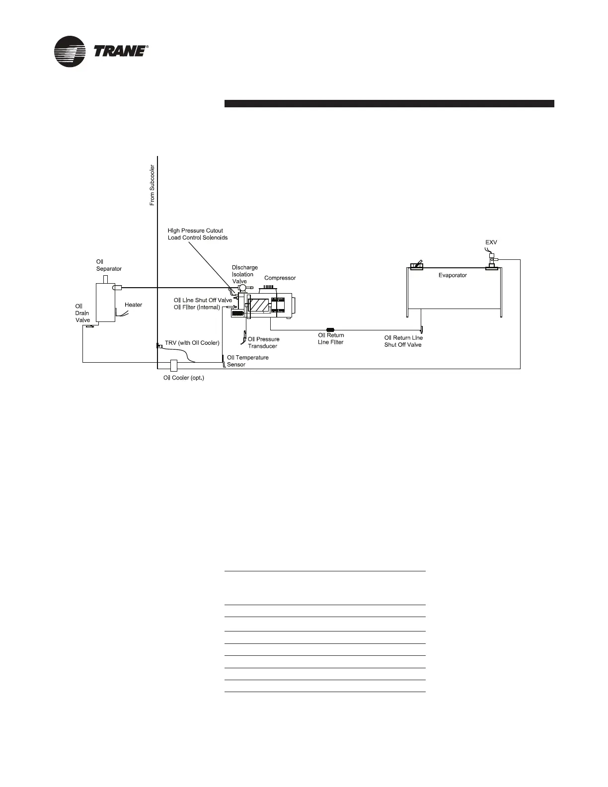
Fig. XI-01 – Oil System Schematic
Oil system consists of the following com-
ponents:
• Compressor
• Oil separator
• Discharge line with service valve
• Oil line from separator to compressor
• Oil line drain (lowest point in system)
• Oil cooler - optional
• Oil temperature sensor
• Oil line shut off valve with are service
connection
• Oil lter (internal to compressor) with
are tting service connection and
schrader valve
• Oil ow control valve (internal to the
compressor after the lter)
• Oil return line from evaporator with shut
off valve and strainer
Refer to Table below - Table for the stan-
dard oil charge for each circuit.
NOTE: Recommendation: check the oil
level in the sump using a sight glass or a
manometer, attached to charging hoses.
Tab. XI-02 – Charge Holding Capabilities on High Side
Circuit Approximate
sump oil level
after
Normal quantity of
oil in refrigeration
70 7 1.1 (0.14)
85
6 1.1 (0.14)
100 7 1.8 (0.23)
120 7 1.8 (0.23)
170 8 3.5 (0.44)
200 8 3.5 (0.44)
240 8 3.5 (0.44)
Circuit varies slightly with efciency and unit conguration
 Loading...