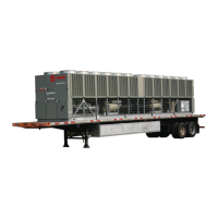
Do you have a question about the Trane RTAC 155 and is the answer not in the manual?
Outlines the general responsibilities of the contractor when installing an RTAC unit.
Recommended methods and precautions for safely lifting and moving the unit.
Strategies for reducing sound and vibration transmission from the unit to the environment.
Requirements for providing a rigid, non-warping foundation to support the unit's operating weight.
Recommended space around the unit for installation and unrestricted access to service points.
Procedures for installing optional neoprene isolators and levelling the unit accurately.
Guidelines for proper water treatment in the chilled-water system to prevent damage and maintain performance.
Importance and installation of pressure-relief valves in the evaporator water system to prevent damage.
Measures to protect the unit and chilled-water system from freezing during subfreezing ambient temperatures.
General guidelines for electrical installation, including safety warnings and wiring compliance.
Provides tables for customer wire selection based on unit size and configuration.
Presents detailed electrical data for compressors, motors, and fans for various unit sizes.
Lists components the installer must provide if not ordered with the unit, such as wiring and disconnect switches.
Guidelines for sizing and selecting power supply wiring according to EN 60204.
Explains how programmable relays can indicate chiller events or states.
Auxiliary control for a customer-specified emergency stop function to trip the unit.
How to use external contacts for Auto/Stop functions to control chiller operation.
A checklist to verify all installation procedures are completed before starting the unit.
Verifying the unit's power supply voltage meets specified criteria and is within range.
Checking for voltage imbalance between phases to prevent motor overheating.
Ensuring correct phase sequence (A-B-C) for proper motor rotation and to prevent damage.
Steps to follow after pre-start checkout, including setting CH.530 values and checking valves.
Procedures for starting the unit after a seasonal shutdown, including valve checks and filling circuits.
Steps to follow to restart the unit after a period of extended shutdown.
Importance of proper oil and refrigerant charge for unit performance and environmental protection.
Procedure for charging refrigerant into the unit, emphasizing safety and water flow.
Steps for replacing the refrigerant filter element, including indications for replacement.
| Model | RTAC 155 |
|---|---|
| Type | Air-Cooled Chiller |
| Cooling Capacity | 155 tons |
| Refrigerant | R-134A |
| Power Supply | 460V/3Ph/60Hz |
| Sound Power Level | 85 dBA |


