EasyManua.ls Logo

Trane TAM7B0C60H51SA User Manual

Trane TAM7B0C60H51SA
44 pages
To Next Page IconTo Next Page
Page #1 background imageLoading...
Page #1 background image
18-GJ06D2-1
Convertible Air Handlers
2 – 5 Ton
TAM7A0A24H21SB
TAM7A0B30H21SB
TAM7A0C36H31SB
TAM7A0C42H31SB
TAM7A0C48H41SB
TAM7A0C60H51SB
TAM7B0C60H51SA
The TAM7 air handlers will only use the following internal
electric heaters:
Installer’s Guide
ALL phases of this installation must comply with NATIONAL, STATE AND LOCAL CODES
Important: This Document is customer property and is to remain with this unit. Please return to service information
pack upon completion of work.
Important: These instructions do not cover all variations
in systems nor provide for every possible contingency
to be met in connection with the installation. Should
further information be desired or should particular
problems arise which are not covered sufficiently for the
purchaser’s purposes, the matter should be referred to
your installing dealer or local distributor.
See the TAM7 Service Facts document for
information on reading the Control Board LEDs, Air
Flow Tables and Troubleshooting Flowcharts.
Note: The manufacturer recommends installing
ONLY A.H.R.I. approved, matched indoor and outdoor
systems. Some of the benefits of installing approved
matched indoor and outdoor split systems are maximum
efficiency, optimum performance, and the best overall
system reliability.
Note: Condensation may occur on the surface of the air
handler when installed in an unconditioned space. When
units are installed in unconditioned spaces, verify that
all electrical and refrigerant line penetrations on the air
handler are sealed completely.
Note: Duct heaters cannot be applied
with this air handler.
Scan to see the
TAM7 Trouble-
shooting Video
Library.
BAYEVAC05BK1AA
BAYEVAC05LG1AA
BAYEVAC08BK1AA
BAYEVAC08LG1AA
BAYEVAC10BK1AA
BAYEVAC10LG1AA
BAYEVBC15BK1AA
BAYEVBC20BK1AA
BAYEVCC25BK1AA
BAYEVAC10LG3AA
BAYEVBC15LG3AA
Question and Answer IconNeed help?

Do you have a question about the Trane TAM7B0C60H51SA and is the answer not in the manual?

Trane TAM7B0C60H51SA Specifications

General IconGeneral
Model NumberTAM7B0C60H51SA
CategoryAir Handlers
Nominal Capacity (Tons)5
Voltage208/230V
Phase1
Blower TypeVariable Speed
RefrigerantR-410A
Nominal Heating Capacity60, 000 BTU
Maximum External Static Pressure0.8 in. wg

Summary

Safety Information

General Safety Warnings

Covers electrical hazards, vapors, sharp edges, and corrosion risks.

Unit Design and Preparation

Cabinet Design and Panel Access

Details cabinet penetration rules and access panel removal.

Unit Preparation and Accessories

Covers checking for damage, orientation, and accessory kits.

Installation Procedures

Cabinet Disassembly for Installation

Step-by-step guide for disassembling the unit's cabinet for tight spaces.

Unit Placement and Carrying

Guidelines for safely carrying and positioning the unit at the installation site.

Location Considerations and Dimensions

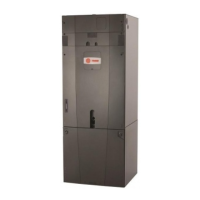
Details unit dimensions, weight, and clearances.

Application Specific Location Notes

Guidance for non-ducted, ducted applications, and additional prep considerations.

Vertical and Horizontal Unit Setting

Instructions for setting units in vertical and horizontal positions, including coil securing.

Ductwork and Refrigerant Line Connections

Procedures for connecting ductwork and details on refrigerant line sizes.

Refrigerant Line Brazing Process

Detailed steps for brazing refrigerant lines, emphasizing safety and technique.

Condensate Drain Piping Installation

Guidelines and procedures for connecting and installing the condensate drain system.

Electrical, Configuration, and Start-Up

Low Voltage Wiring and Hook-up

Instructions for low voltage wiring, max lengths, and hook-up.

Dip Switch Settings and Airflow Control

Configuration of dip switches for tonnage, stages, CFM, and blower timing.

High Voltage Power Supply

Guidelines for connecting the high voltage power supply to the unit.

Filter Requirements and System Start-Up

Information on filter requirements and procedures for initial system start-up.

System Operation and Checkout

Sequence of Operation

Detailed explanation of system operation in cooling, heating, and defrost modes.

Final Checkout Procedures

Checklist for verifying proper installation and system performance.

Related product manuals