EasyManua.ls Logo

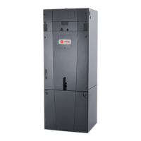
Trane TAM4A0A18S11SB User Manual

Trane TAM4A0A18S11SB
251 pages
To Next Page IconTo Next Page
Page #1 background imageLoading...
Page #1 background image

Table of Contents

Question and Answer IconNeed help?

Do you have a question about the Trane TAM4A0A18S11SB and is the answer not in the manual?

Trane TAM4A0A18S11SB Specifications

General IconGeneral
Model NumberTAM4A0A18S11SB
CategoryAir Handlers
Nominal Cooling Capacity1.5 tons
RefrigerantR-410A
Blower MotorMulti-speed
Voltage208/230V
Phase1
Maximum Overcurrent Protection15A
CabinetGalvanized steel
Airflow Range400- CFM
InsulationFoil-faced insulation
Filter TypeDisposable

Summary

Safety Information

LIVE ELECTRICAL COMPONENTS!

Warning about electrical hazards during service and installation.

HAZARDOUS VAPORS!

Warning to avoid installing air handlers near fossil fuel devices.

Unit Preparation

Prepare The Unit For Installation

Steps to take before moving the unit to its final installation site.

Optional Cabinet Disassembly

Pre-Installation Requirements

Receiving Checklist

Steps for inspecting the unit upon arrival for damage and completeness.

Resolving Shipping Damage

Storage Recommendations

Preparing the Unit Site

Roof Curb Installation Checklist

Unit Dimensions and Weights

Service Clearances

Required clearances for unit service and maintenance.

Installation - Mechanical

Lifting and Rigging

Procedures for safely lifting and rigging the unit.

Remove Shipping Tie-Downs

Instructions for removing shipping restraints before placement.

General Lifting Considerations

Lifting Inlet and Exhaust Hoods and External Pipe Cabinet (Chase)

Forklifting Considerations for Indoor Units Size 3-30

Unit Placement and Assembly

Using Integral Base Frame

Section-to-Section Assembly

Vertical SDU/Winterizer Indoor Air Handler Assembly

Component Installation Requirements

Filter Installation

Filter Placement

Seismic Isolation Requirements

Anchor Requirements

Guidelines for seismic anchoring of the unit.

Anchor Pattern

Damper Sections

Damper Torque Requirements

Torque specifications for damper actuators based on unit size.

Opposed-Blade and Parallel-Blade Dampers

Damper Connections

Bottom Opening Duct Installation

Traq Damper Connections

External Face-and-Bypass Connections

Coil Piping and Connections

Refrigerant Coil Piping

Information and diagrams for refrigerant coil piping.

Drain Pan Trapping

Steam Coil Piping

Water Coil Piping

Liquid Lines

Line Sizing

Critical sizing for successful split-system liquid line applications.

Suction Lines

Line sizing

Sizing for oil return and system efficiency.

Components

Installation - Electrical

High Voltage Power Supply

Requirements for the high voltage power supply.

Make Electrical Connections

Step-by-step procedures for making electrical connections.

Controls Interface

Calibrating the operator display

Start-Up

Pre-Startup Checklist

A checklist of tasks to complete before unit startup.

General Checks

Fan-Related Checks

Coil-Related Checks

Motor-Related Checks

Unit Operation

Calculate Motor Voltage Imbalance

Method to calculate motor voltage imbalance.

Tension the Fan Belt

Instructions for adjusting fan belt tension.

Determine Fan Speed

Airflow Measuring Systems

Constant Factor K

Troubleshooting

Routine Maintenance

Maintenance Checklist

A periodic maintenance schedule for the unit.

Air Filters

Drain Pans

Bearing Set Screw Alignment

Fan Bearing Lubrication

Refrigerant Coils

Coil Winterization

Cleaning Porous Surfaces

Ultraviolet (UV) Light Maintenance

Disposal of Bulbs

Related product manuals