EasyManua.ls Logo

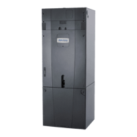
Trane TAMXA0C42V41DA User Manual

Trane TAMXA0C42V41DA
48 pages
To Next Page IconTo Next Page
Page #1 background imageLoading...
Page #1 background image
SSAAFFEETTYY WWAARRNNIINNGG
Only qualified personnel should install and service the equipment. The installation, starting up, and servicing of heating, ventilating, and air-conditioning
equipment can be hazardous and requires specific knowledge and training. Improperly installed, adjusted or altered equipment by an unqualified person
could result in death or serious injury. When working on the equipment, observe all precautions in the literature and on the tags, stickers, and labels that
are attached to the equipment.
September 2021
1188--GGJJ8899DD11--11DD--EENN
Link Communicating / Variable Speed Outdoor Compatible
Convertible Air Handlers
TAMXA0A24V21DA
TAMXA0B30V31DA
TAMXA0C36V31DA
TAMXA0C42V41DA
TAMXA0C48V41DA
TAMXA0C60V51DA
TM
The Diagnostics Mobile App is available by scanning a
QR code located inside this unit or by searching for the
Link Diagnostics app in your App Store.
NNoottee:: “Graphics in this document are for representation only. Actual
model may differ in appearance.”
NNoottee:: For use with BAYEA series heaters ONLY.
Installer’s Guide
Question and Answer IconNeed help?

Do you have a question about the Trane TAMXA0C42V41DA and is the answer not in the manual?

Trane TAMXA0C42V41DA Specifications

General IconGeneral
Model NumberTAMXA0C42V41DA
CategoryAir Handlers
Nominal Capacity (Tons)3.5
Phase1
RefrigerantR-410A
Width (in)21
Depth (in)21
Nominal Heating Capacity42, 000 BTU/h
Voltage208/230
Airflow1400 CFM
Airflow Range800-1, 600 CFM

Summary

Safety Section Air Handlers

General Safety Warnings

Crucial safety precautions including electrical hazards, refrigerant, and sharp edges.

Installer Guide Notes

Unit Design and Panel Access

Unit Install Preparation

Placing Unit at Location

Additional Unit Preparation Considerations

Setting the Unit – Vertical Installation

Setting the Unit – Horizontal Installations

Refrigerant Line

Line Sizes and System Layout

Specifications for refrigerant line connection sizes and a diagram of the system layout with sensor locations.

Refrigerant Line Brazing

Refrigerant Line Preparation for Brazing

Procedures for preparing refrigerant lines, removing panels, and handling heat-sensitive components before brazing.

Field Line Set Connection and Brazing

Steps for connecting the field line set and performing brazing operations, including sensor protection.

Pressure Testing and Evacuation

Procedures for pressurizing, leak testing, and evacuating the refrigerant system to proper micron levels.

Condensate Drain Piping

Electrical – Low Voltage

Low Voltage Wiring Hook-up Instructions

Instructions for routing low voltage wiring, including strain relief and removing the coil panel for access.

Control Board Installation and Orientation

Procedures for accessing, orienting, and reinstalling the control board for various installation types.

Link Communicating Hook-Up Diagrams

Wiring diagrams illustrating low voltage connections for communicating systems, distribution boards, and user interfaces.

Control Panel Reinstallation

Electrical – High Voltage

High Voltage Power Supply and Conduit Entry

Guidelines for high voltage power connection, compliance, and selecting conduit entry points.

High Voltage Wiring Connections

Procedures for connecting high voltage L1, L2, and ground wiring to the unit, including options for electric heaters.

System Start Up

Final System Power-Up Procedure

Final steps for powering up the system, including panel securement, power connection, and thermostat setting.

Sequence of Operation

Checkout Procedures

Final Installation Checklist

A comprehensive checklist to ensure all installation requirements and safety checks have been completed successfully.

Related product manuals