24
18-HD82D1-1B-EN
XR724 INSTALLER’S GUIDE
VS Air Handler &
Electric Heat
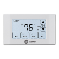
Heat/Cool Diagram 9: 1 or 2 Stage Cooling w/TEM8, TEM6 Variable Speed Air Handler
G
W1
Y1
R
B/C
Y
2
BK
W2
One or Two Stage
Cooling Only
Y 1
R
B
Y2
Notes:
1. Cut/remove the factory installed “BK” jumper at the indoor unit
2. “Y2” & “R” connections at outdoor are only required for two
stage units
3. Jumper “W2” to “W3” if three stages of indoor heat are available
4. For non-Trane/American Standard Indoor units “BK” is not
connected and “Y1”/”Y2” must be connected at indoor unit.
Sensor Options in the Installer Settings/Sensor Settings menu
Remote Sensor (connect to the RS terminals)
- None
- Replaces internal sensor
- Average with internal sensor
Outdoor Temp Sensor (connect to the ODT terminals)
- None
- Outdoor
Caution: Do not run sensor wires in the same bundle with HVAC
wires. Keep away from high voltage wiring to avoid interference.
Remote Temperature Sensor Connections and Operation:
(Note 1)
(Note 4)
(Note 3)
Aux relay
outputs
RS
C
RS
R
ODT
W1
W2
BK
ODT
NO
C
Y1
NC
Y2
O/B
G
Thermostat Connection
Outdoor
Sensor
Remote
Sensor
W3
(Note 2)
(Note 2)
Non-VS
Air Handler &
Electric Heat
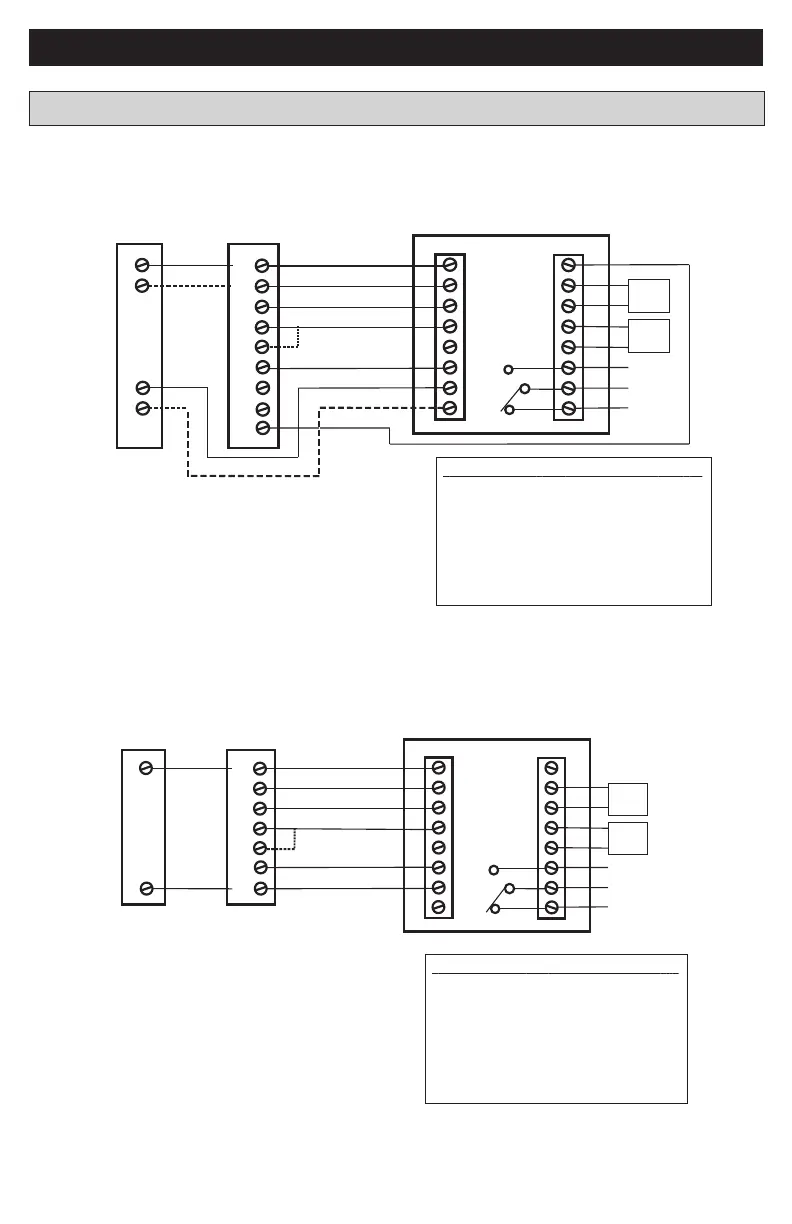
Heat/Cool Diagram 10: 1 Stage Cooling w/non-Variable Speed Air Handler
(Excludes Hyperion/Forefront/TEM3 Air Handlers)
G
W1
R
B/C
W2
One Stage
Cooling Only
Y
B
Notes:
1. Jumper “W2” to “W3” if three stages of indoor heat
are available
Sensor Options in the Installer Settings/Sensor Settings menu
Remote Sensor (connect to the RS terminals)
- None
- Replaces internal sensor
- Average with internal sensor
Outdoor Temp Sensor (connect to the ODT terminals)
- None
- Outdoor
Caution: Do not run sensor wires in the same bundle with HVAC
wires. Keep away from high voltage wiring to avoid interference.
Remote Temperature Sensor Connections and Operation:
(Note 1)
Aux relay
outputs
RS
C
RS
R
ODT
W1
W2
BK
ODT
NO
C
Y1
NC
Y2
O/B
G
Thermostat Connection
Outdoor
Sensor
Remote
Sensor
W
3
Y
Heat/Cool Wiring Diagrams
 Loading...