8 18-DE01D1-8
Installer’s Guide
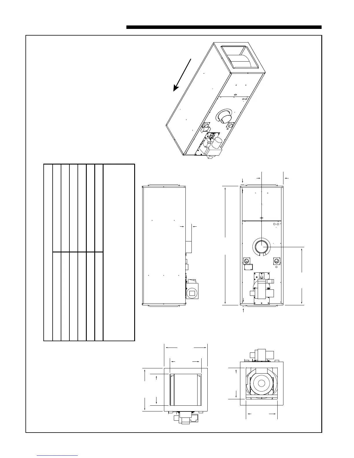
61.25
11.12
29.82
16.13
16.13
16.13
22.25
22.25
Downflow / Horizontal - Front FlueDownflow / Horizontal - Front Flue
0.75
0.75
16.13
22.25
3.23
AI
RF
L
O
W
MINIMUM CLEARANCE TO COMBUSTIBLE MATERIALS
Furnace casing sides and rear 3"
Front furnace casing to closet door1 8"
Furnace flue pipe / vent connector 9"
Furnace casing top 3"
Supply air plenum (any side) 3"
Supply air ducts within 6 feet of the furnace. 3"
Notes:
1 The Horizontal / Downflow model requires 22" from the front casing of the furnace to the
closet door.
2 Adequate clearance from the supply end surface of the furnace casing to combustible
materials are provided by the design of the accessory mounting base when used with the
Horizontal / Downflow furnace model applied in the Downflow configuration.
TDF1MO87A936, 48, V3, V5SA OUTLINE DRAWING
(ALL DIMENSIONS ARE IN INCHES)