Installation
32 RT-SVX22M-EN
disconnect switch (UDC) or circuit breaker (UCB). If neither
a factory mounted non-fused disconnect switch (UDC) or
circuit breaker (UCB) was factory mounted, field wiring
connections should be terminated in the control box at
Compressor Contactor # 1 (CC1).
Provide proper grounding for the unit in accordance with
local and national codes.
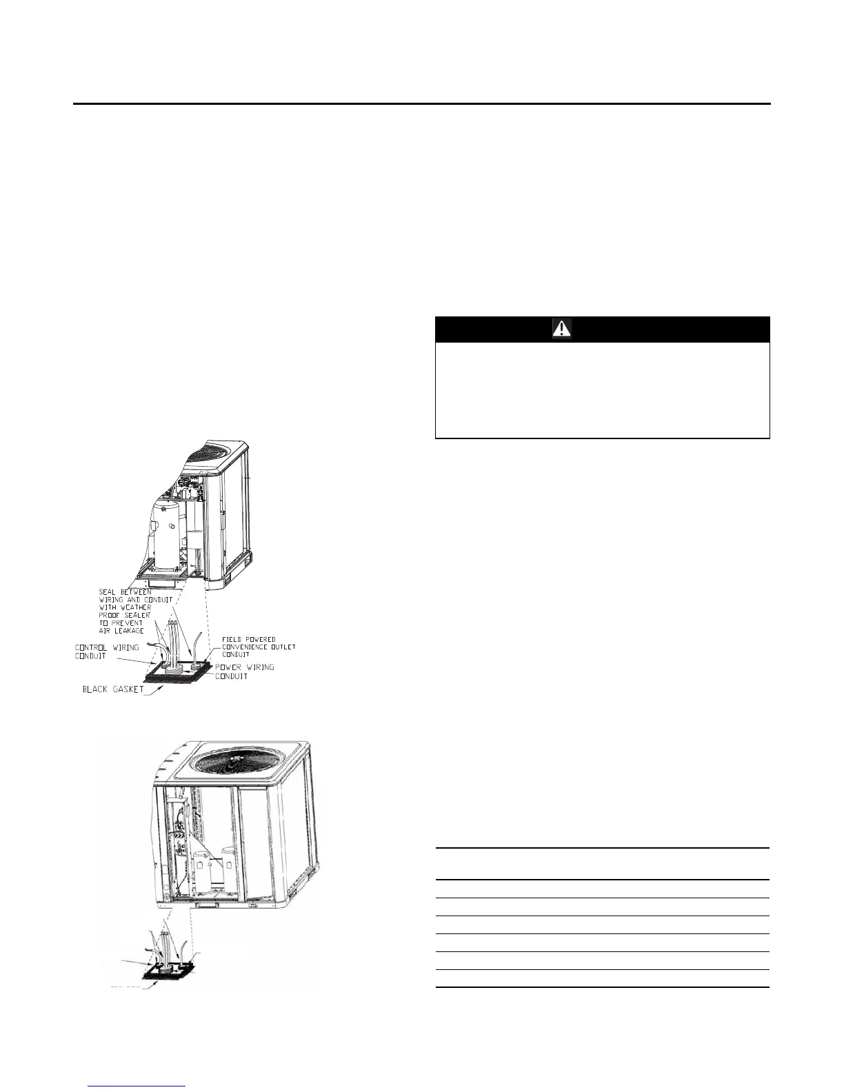
Note: Black Gasket is shipped from the factory and is
located in the literature ShipWith bag in the control
box.Apply Black Gasket around conduit plate on all
4 sides after installation to prevent air leak age from
the building entering the electrical enclosures.
Note: Seal between wiring and conduit with Black Gasket
or weather proof sealer to prevent air leakage from
the building entering the electrical enclosures.Also
seal around conduit and wiring at all roof and curb
penetrations.
Field Installed Control Wiring
An overall layout of the various control options available
with the required number of conductors for each control
device is illustrated in Figure 52, p. 39.
Control Power Transformer
The 24 volt control power transformers are to be used only
with the accessories called out in this manual.
Transformers rated greater than 50 VA are equipped with
internal circuit breaker s. If a circuit breaker trips, turn “Off”
all power to the unit before attempting to reset it.
The transformer is located in the control panel.The circuit
breaker is located on the left side of the transformer and
can be reset by pressing in on the black reset button.
Controls using 24 VAC
Before installing any connecting wiring, refer to “Unit
Dimensions,” p. 14 for the electrical access locations
provided on the unit and Table 5, p. 32 or Table 6, p. 33 for
AC conductor sizing guidelines, and;
1. Use copper conductors unless otherwise specified.
2. Ensure that the AC control wiring between the controls
and the unit’s termination point does not exceed three
(3) ohms/conductor for the length of the run.
Note: Resistance in excess of 3 ohms per conductor may
cause component failure due to insufficient AC
voltage supply.
Note: Be sure to check all loads and conductors for
grounds, shorts, and mis-wiring.
3. Do not run the AC low voltage wiring in the same
conduit with the high voltage power wiring.
4. Route low voltage wiring per illustrations on page 34.
Figure 36. All units except 10 ton high efficiency with
hot gas reheat dehumidification.
Figure 37. 10 ton high efficiency
CONTROL WIRING
CONDUIT
BLACK GASKET
CONTROL WIRING
CONDUIT
FIELD POWERED
CONVENIENCE OUTLET
CONDUIT
SEAL BETWEEN
WIRING AND
CONDUIT WITH
WEATHER PROOF
SEALER TO PREVENT
AIR LEAKAGE
WARNING
Hazardous Voltage!
Disconnect all electric power, including remote
disconnects before servicing. Follow proper lockout/
tagout procedures to ensure the power can not be
inadvertently energized. Failure to disconnect power
before servicing could result in death or serious injury.
Table 5. Electromechanical thermostat 24V AC
conductors with ReliaTel™ units
Distance from Unit to
Control Recommended Wire Size
000 - 460 feet 18 gauge
000 - 140 m .75 mm2
461 - 732 feet 16 gauge
141 - 223 m 1.3 mm2
733 - 1000 feet 14 gauge
224 - 305 m 2.0 mm2