6
owner's manual
6. CONSTRAINT COOLING AND QUERY
Constraint Cooling
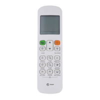
Once pressing the constraint cooling button(see the chart on
the right), all the indoor unit will be on forced cooling mode and
the wind speed is HIGH.
SW2 Query Instructions
Fig.6-1
MAIN BOARD
(OUTDOOR UNIT)
Query button
Constraint cooling button
CHECK
COOL
Table.6-1
1
2
0,1,2,3
0,1,2,3
0,1,2,3
0,1,2,3
8,10,12,14,16
3
4
5
6
7
8
9
10
11
12
13
14
15
16
17
18
19
20
21
22
23
24
25
26
27
28
29
30
31
32
33
34
35
36
37
38
39
40
Outdoor unit address 0. --
1. --
2. --
3. --
4. --
5. --
6. --
7. --
8. --
9. --
10. --
11. --
12. --
13. --
14. --
15. --
16. --
17. --
18. --
19. --
20. --
21. --
22. --
23. --
24. --
25. --
26. --
27. --
28. --
29. --
30. --
31. --
32. --
33. --
34. --
35. --
36. --
37. --
38. --
39. --
Note Display content Normal display
Outdoor unit itself capacity
Modular outdoor unit qty.
Operation mode
Available for main unit
0,2,3,4,5,6
No.
Total capacity of outdoor unit
Night noise control mode
Static pressure mode
Capacity requirement
Cooling capacity
Heating capacity
Auxiliary unit only display capacity of main mode
Auxiliary unit only display capacity of main mode
T4 ambient temp. revision of cooling capacity
T4 ambient temp. revision of heating capacity
The outdoor unit actual operation capacity Capacity requirement
Speed of fan A
Speed of fan B
0, 1,······,14,15
0, 1,······,14,15
T2 average temp. Actual value
Actual value
Actual value
Actual value
Actual value
Actual value
Actual value
Actual value
Actual value+30
Actual value
Actual value
Actual value
Actual value
Actual value
Actual value÷8
Actual value÷8
Actual value×10
Actual value÷10
Actual value÷10
T2B average temp.
T3 pipe temp. (Left pipe temp. )
T5 pipe temp. ( Right pipe temp. )
T4 ambient temp.
Discharge temp.of inverter compressor B
Discharge temp.of inverter compressor A
Discharge pressure corresponding to the saturation temperature
The minimum overheating temp. of discharge
Current of inverter compressor A
Current of inverter compressor B
Opening angle of EXV A
Opening angle of EXV B
High pressure
Reserve
Reserve
Reserve
Qty. of indoor units
Qty. of cooling indoor units
Qty. of heating indoor units
That can communicate with indoor units
DC voltage A
DC voltage B
Display code 8.8.8
State of the evaporator or condenser
Check end
Remove fault number of times
Modual temp.
 Loading...