26
4 Normal Operation Control
4.1 Component Control during Normal Operation
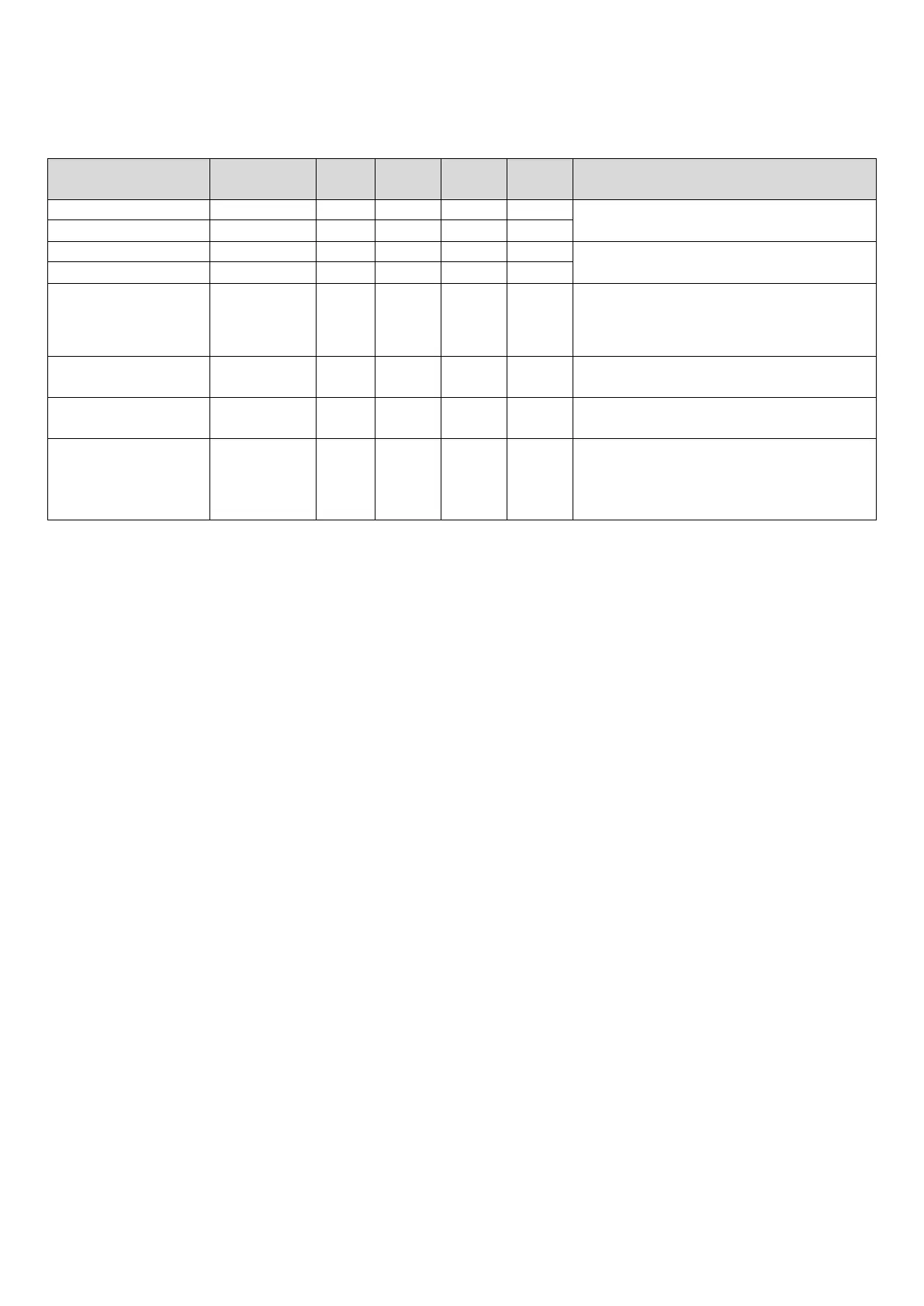
Table 3-4.1: Component control during normal cooling operation
Component
Wiring diagram
8-12HP 14-16HP 18-22HP 24-30HP Control functions and states
● ● ● ●
Controlled according to load requirement
● ●
● ● ● ●
Controlled according to discharge pressure
● ●
E
valve A
EXVA ● ● ● ●
Position (steps) from 0 (fully closed) to 3000 (fully
open), controlled according to discharge
temperature
Solenoid valve (Liquid
SV2 ● ● ● ● Controlled according to discharge temperature
S
olenoid valve (oil
balance)
SV4 ● ● ● ●
Open regularly
S
(refrigerant bypass)
SV7 ● ● ● ●
Controlled according to
discharge pressure,compressor running frequency,
discharge superheating degree, load requirement,
discharge temperature and discharge pressure.
4.2 Compressor Output Control
The compressor rotation speed is controlled according to the load requirement. Before compressor startup, the outdoor
units first estimate the indoor unit load requirement according to the nominal capacity of indoor units currently running,
and then correct for ambient temperature. The compressors then start up according to the corrected load requirement.
During operation the compressors are controlled according to the nominal capacity of indoor units currently running and
the indoor unit heat exchanger temperatures. If the actual load requirement can be provided by one unit alone, then only
one unit starts up. If the actual load requirement requires all outdoor unit modules to operate, the weighted average
actual load requirement is sent to each module and each module operates according to this distributed load
requirement.
4.3 Compressor Step Control
The compressor speed can be altered in increments of 1 rps (rotations per second) and decrease of 2rps.
4.4 Operating Priority and Rotation of Compressors
Figures 3-4.1 to 3-4.3 show the compressor operating priority and rotation in systems with one, two and three outdoor
units. In units with two compressors, inverter compressor A (BP1) operates in priority to inverter compressor B (BP2). In
multi-unit systems, units operate in rotation. In Figures 3-4.2 and 3-4.3 the master unit and slave units 1 and 2 are shown
from left to right in that order, and the circled numbers (
①, ②, ③) indicate the rotation sequence.
 Loading...