Home
Trane
Air Conditioner
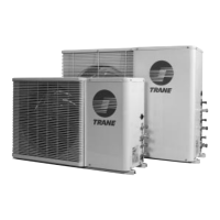
TVR Pro CO Series
Trane TVR Pro CO Series User Manual
4
of 1
of 1 rating
118 pages
Give review
Manual
Specs
To Next Page
To Next Page
Loading...
Ser
vice Manual
T
VR Pro CO
Series
Commercial A
ir Co
nditio
ners
R410A
4TVY0077H8000AA
4TVY0096H8000AA
4TVY0115H8000AA
4TVY0140H8000AA
4TVY0155H8000AA
4TVY0170H8000AA
4TVY0192H8000AA
4TVY0210H8000AA
4TVY0229H8000AA
4TVY0249H8000AA
4TVY0268H8000AA
4TVY0290H8000AA
2
Table of Contents
Front Cover
1
CONTENTS
2
Part 1 TVR Pro CO General Information_20210701
4
Part 2 Component Layout and Refrigerant Circuits_20210701
13
1 Layout of Functional Components
14
2 Piping Diagrams
17
3 Refrigerant Flow Diagrams
21
Part 3 Control_20210701
24
1 General Control Scheme Flowchart
25
2 Stop Operation
26
3 Startup Control
26
3.1 Compressor Startup Delay Control
26
3.2 Startup Control for Cooling Operation
26
4 Normal Operation Control
27
4.1 Component Control during Normal Operation
27
4.2 Compressor Output Control
27
4.3 Compressor Step Control
27
4.4 Operating Priority and Rotation of Compressors
27
4.5 Electronic Expansion Valve Control
28
4.6 Outdoor Fan Control
29
5 Protection Control
30
5.1 High Pressure Protection Control
30
5.2 Low Pressure Protection Control
30
5.3 Discharge Temperature Protection Control
30
5.4 Compressor and Inverter Module Protection Control
31
6 Special Control
32
6.1 Outdoor Unit Duty Cycling
32
6.2 Oil Return Operation
33
Part 4 Field Settings_20210701
34
1 Outdoor Unit Field Settings
35
1.1 PCB Switches and Switch Settings
35
1.2 Modes Set on Main PCB
37
1.2.1 Silent time setting
37
1.2.1.1 Night silent time setting
37
1.2.1.2 Silent mode setting
38
1.2.1.3 Maximum fan speed and capacity output control in different silent mode
38
Part 5 Electrical Components and Wiring Diagrams_20210701
39
Part 6 Diagnosis and Troubleshooting_20210701
55
1 Error Code Table
56
2 Troubleshooting
57
2.1 Warning
57
2.2 E0: Communication error between outdoor units
58
2.2.1 Digital display output
58
2.2.2 Description
58
2.2.3 Trigger / recover condition
58
2.2.4 Possible causes
58
2.2.5 Procedure
59
2.3 E2: Communication error between indoor and master unit
60
2.3.1 Digital display output
60
2.3.2 Description
60
2.3.3 Trigger / recover condition
60
2.3.4 Possible causes
60
2.3.5 Procedure
61
2.4 E4: Temperature sensor (T3/T4) error
62
2.4.1 Digital display output
62
2.4.2 Description
62
2.4.3 Trigger / recover condition
62
2.4.4 Possible causes
62
2.4.5 Procedure
63
2.5 E5: Abnormal power supply voltage
64
2.5.1 Digital display output
64
2.5.2 Description
64
2.5.3 Trigger / recover condition
64
2.5.4 Possible causes
64
2.5.5 Procedure
65
2.6 E7: Temperature sensor (T7C1/2) error
66
2.6.1 Digital display output
66
2.6.2 Description
66
2.6.3 Trigger / recover condition
66
2.6.4 Possible causes
66
2.6.5 Procedure
67
2.7 E8: Outdoor unit address error
68
2.7.1 Digital display output
68
2.7.2 Description
68
2.7.3 Trigger / recover condition
68
2.7.4 Possible causes
68
2.7.5 Procedure
69
2.8 xE9: EEPROM mismatch
70
2.8.1 Digital display output
70
2.8.2 Description
70
2.8.3 Trigger / recover condition
70
2.8.4 Possible causes
70
2.8.5 Procedure
71
2.9 xF1: DC bus voltage error
72
2.9.1 Digital display output
72
2.9.2 Description
72
2.9.3 Trigger / recover condition
72
2.9.4 Possible causes
72
2.9.5 Procedure
73
2.10 F3, F5: Temperature sensor (T6B/T6A) error
74
2.10.1 Digital display output
74
2.10.2 Description
74
2.10.3 Trigger / recover condition
74
2.10.4 Possible causes
74
2.10.5 Procedure
75
2.11 F6: Electronic expansion valve connection error
76
2.11.1 Digital display output
76
2.11.2 Description
76
2.11.3 Trigger / recover condition
76
2.11.4 Possible causes
76
2.11.5 Procedure
77
2.12 xH0: Communication error
78
2.12.1 Digital display output
78
2.12.2 Description
78
2.12.3 Trigger / recover condition
78
2.12.4 Possible causes
78
2.12.5 Procedure
78
2.13 H2, H3: Slave units decreased/increased
80
2.13.1 Digital display output
80
2.13.2 Description
80
2.13.3 Trigger / recover condition
80
2.13.4 Possible causes
80
2.13.5 Procedure
81
2.14 xH4: Inverter module protection
82
2.14.1 Digital display output
82
2.14.2 Description
82
2.14.3 Trigger / recover condition
82
2.14.4 Possible causes
82
2.14.5 Specific error codes for xH4 inverter module protection
82
2.14.6 L0: Inverter module protection
84
2.14.7 L1: DC bus low voltage protection
85
2.14.8 L2: DC bus high voltage protection
86
2.14.9 L4: MCE error
87
2.14.10 L7: Phase sequence error
88
2.14.11 L8: Compressor frequency variation greater than 15Hz within one second protection
89
2.14.12 Compressor replacement procedure
90
2.15 H7: Unmatched total number of indoor units
93
2.15.1 Digital display output
93
2.15.2 Description
93
2.15.3 Trigger / recover condition
93
2.15.4 Possible causes
93
2.15.5 Procedure
94
2.16 H8: High pressure sensor error
95
2.16.1 Digital display output
95
2.16.2 Description
95
2.16.3 Trigger / recover condition
95
2.16.4 Possible causes
95
2.16.5 Procedure
96
2.17 yHd: Slave unit malfunction
97
2.17.1 Digital display output
97
2.17.2 Description
97
2.17.3 Trigger / recover condition
97
2.17.4 Possible causes
97
2.17.5 Procedure
98
2.18 P1: Discharge pipe high pressure protection
99
2.18.1 Digital display output
99
2.18.2 Description
99
2.18.3 Trigger / recover condition
99
2.18.4 Possible causes
99
2.18.5 Procedure
99
2.19 P2, H5: Suction pipe low pressure protection
101
2.19.1 Digital display output
101
2.19.2 Description
101
2.19.3 Trigger / recover condition
101
2.19.4 Possible causes
101
2.19.5 Procedure
102
2.20 xP3: Compressor current protection
103
2.20.1 Digital display output
103
2.20.2 Description
103
2.20.3 Trigger / recover condition
103
2.20.4 Possible causes
103
2.20.5 Procedure
103
2.21 P4, H6: Discharge temperature protection
105
2.21.1 Digital display output
105
2.21.2 Description
105
2.21.3 Trigger / recover condition
105
2.21.4 Possible causes
105
2.21.5 Procedure
105
2.22 P5: Outdoor heat exchanger temperature protection
107
2.22.1 Digital display output
107
2.22.2 Description
107
2.22.3 Trigger / recover condition
107
2.22.4 Possible causes
107
2.22.5 Procedure
108
2.23 P9, H9: Fan module protection
109
2.23.1 Digital display output
109
2.23.2 Description
109
2.23.3 Trigger / recover condition
109
2.23.4 Possible causes
109
2.23.5 Procedure
109
2.24 PL, C7: Inverter module temperature protection
111
2.24.1 Digital display output
111
2.24.2 Description
111
2.24.3 Trigger / recover condition
111
2.24.4 Possible causes
111
2.24.5 Procedure
112
2.25 PP: Compressor discharge insufficient superheat protection
113
2.25.1 Digital display output
113
2.25.2 Description
113
2.25.3 Trigger / recover condition
113
2.25.4 Possible causes
113
2.25.5 Procedure
114
3 Appendix to Part 6
115
3.1 Temperature Sensor Resistance Characteristics
115
3.2 Normal Operating Parameters of Refrigerant System
118
4
Based on 1 rating
Ask a question
Give review
Questions and Answers:
Need help?
Do you have a question about the Trane TVR Pro CO Series and is the answer not in the manual?
Ask a question
Trane TVR Pro CO Series Specifications
General
Refrigerant
R-410A
Phase
1
Warranty
10-year limited warranty on compressor, 5-year limited warranty on parts
Cooling Capacity (Tons)
2 - 5
Voltage
208/230
Related product manuals
Trane TVR Pro CO 4TVY0096H8000AA
118 pages
Trane TVR Pro CO 4TVY0140H8000AA
118 pages
Trane TVR Pro CO 4TVY0170H8000AA
118 pages
Trane TVR Pro CO 4TVY0192H8000AA
118 pages
Trane TVR Pro CO 4TVY0210H8000AA
118 pages
Trane TVR Pro CO 4TVY0229H8000AA
118 pages
Trane THC037E
68 pages
Trane Voyager TC*
108 pages
Trane TTZ048A100A1
6 pages
Trane TTA120D300AA
11 pages
Trane TTA090A series
32 pages
Trane TTA120C series
32 pages