Do you have a question about the Trane TVR Pro CO Series and is the answer not in the manual?
| Refrigerant | R-410A |
|---|---|
| Phase | 1 |
| Warranty | 10-year limited warranty on compressor, 5-year limited warranty on parts |
| Cooling Capacity (Tons) | 2 - 5 |
| Voltage | 208/230 |
Lists indoor unit types and their capacity ranges, plus fresh air/heat recovery unit capacities.
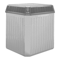
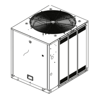
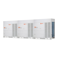
Displays visual examples of various indoor and outdoor unit types.
Shows factory-recommended combinations of outdoor units based on HP.
Defines the permissible ratio between indoor and outdoor unit capacities.
Illustrates the internal components of outdoor units for different HP ranges.
Provides refrigerant circuit diagrams for 8-16HP, 18-22HP, and 24-30HP units.
Shows refrigerant flow during cooling and oil return operations for various unit types.
Outlines the system's control logic, including stop, startup, normal, protection, and special controls.
Explains the conditions that trigger system shutdown or unit stops.
Details compressor startup delays and component control during the initial startup phase.
Covers component control, compressor output, and fan speed adjustments during normal operation.
Details safety controls for high pressure, low pressure, temperature, and module protections.
Explains functions like outdoor unit duty cycling and oil return operation.
Describes how to configure outdoor unit settings using PCB switches.
Shows the physical layout of the main PCB, inverter, and fan modules within the control box.
Identifies and explains the function of various ports and components on the main PCB.
Provides detailed electrical connection diagrams for 8-16HP and 18-30HP units.
A comprehensive list of error codes, their meanings, and required actions for resolution.
Step-by-step guides and procedures for diagnosing and resolving system errors.
Includes reference data such as temperature sensor resistance characteristics.