14 18-CD30D1-12
Installer’s Guide
TABLE 8
MINIMUM CLEARANCE FROM COMBUSTIBLE MATERIALS FOR
UPFLOW/HORIZONTAL AND DOWNFLOW/ HORIZONTAL FURNACES
UNIT LOCATION
FURNACE SURFACE
VERTICAL
CLOSET
HORIZONTAL
CLOSET
HORIZONTAL
ALCOVE / ATTIC
SIDES 0" 1" 0"
BACK 0" 3" 6"
TOP 1" 1" 1"
FRONT 3" 3" 18"
VENT 0" 0" 0"
NOTE: CLEARANCE REQUIRED AT TOP OF PLENUM IS 1"
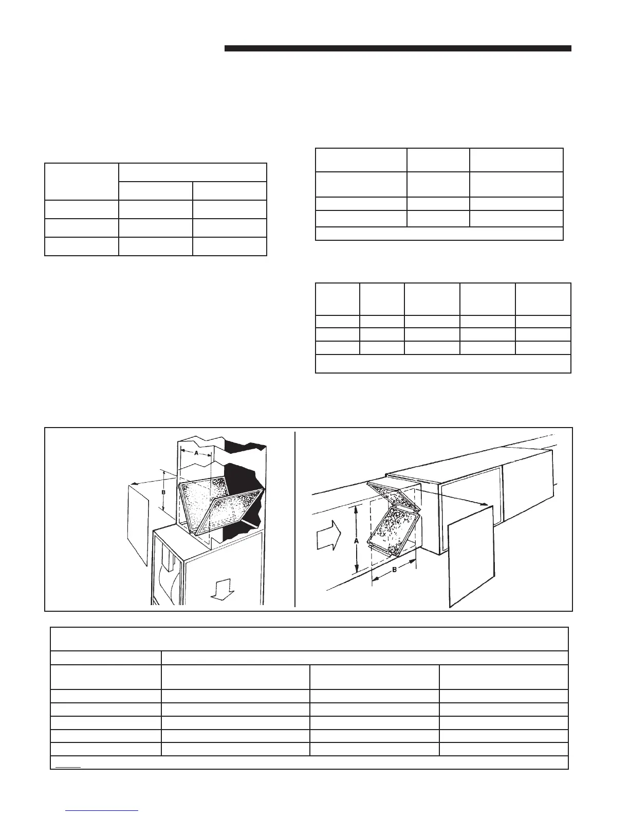
Downflow furnace filters must be located outside the
furnace cabinet. Typical installations are shown in Figure
22. Tables 6 and 7 provide information for installation
of the filter retaining brackets shipped with downflow
furnaces.
TABLE 6
MODELS
NUMBERS
CABINET
WIDTH
FILTER
QTY & SIZE
*DHMB060BCV3VB
*DHMB080ACV3VB
17-1/2" 2 - 14" X 20" X 1"
*DHMC100ACV4VB 21" 2 - 16" X 20" X 1"
*DHMD120BCV5VB 24-1/2" 2 - 16" X 20" X 1"
*First letter may be "A" or "T"
TABLE 7
LOCATING FILTER RETAINER BRACKETS IN DUCTWORK
CABINET
WIDTH
RETURN
DUCT
WIDTH
DIMENSION
"A"
DIMENSION
"B"
FILTER
BRACKET
LOCATION*
17-1/2" 16-1/4" 15" 14" 14-3/8"
21" 19-3/4" 19-1/2" 14" 13-1/8"
24-1/2" 23-1/4" 22" 14" 13-5/8"
* LOCATION DIMENSION IS FROM END OF DUCT AGAINST THE FURNACE TO THE
SCREW HOLES FOR THE BRACKET.
Airflow
DOWNFLOW/
HORIZONTAL
DOWNFLOW
Airflow
s
INSTALLING THE FILTER
The filter may need to be cut to fit the unit depending on
the location of the return air filter.
A score line and the words “CUT HERE” are located
on the end of the filter. If your application requires
cutting the filter, do so as indicted by the score mark.
TABLE 5
UNIT
SIZE
RETURN AIR
BOTTOM SIDE
17-1/2" DO NOT CUT DO NOT CUT
21" DO NOT CUT CUT ON LINE
24-1/2" DO NOT CUT CUT ON LINE
TYPICAL DOWNFLOW FURNACE RETURN AIR
FILTER INSTALLATIONS
Two filters are factory supplied for each downflow
furnace. These furnaces require high velocity type air
filters.