18-CD30D1-12 17
Installer’s Guide
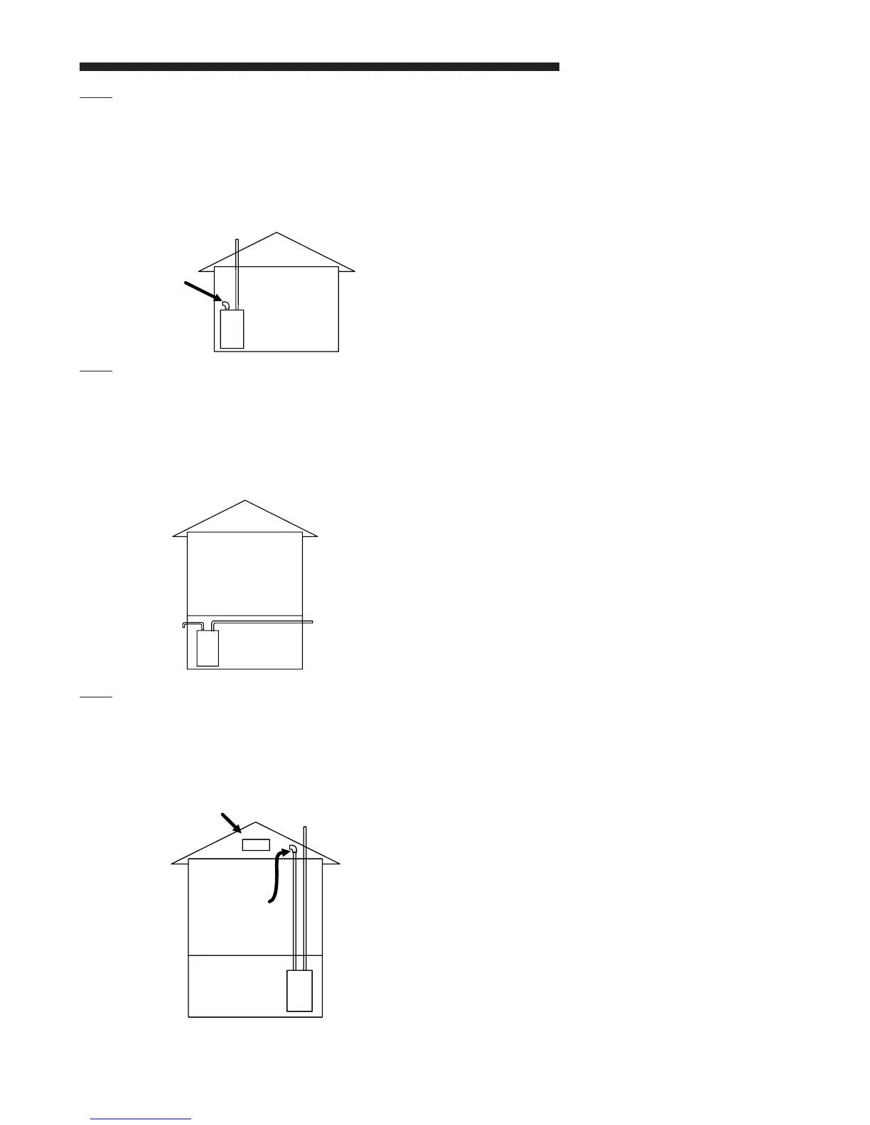
EX. 2 —
Example 2 shows the vent pipe exhausting through the
roof and the inlet air coming from the interior of the house
(See Note). The inlet air coming from the interior of the
house must meet combustion requirements for area, etc.,
as shown in the section AIR FOR COMBUSTION AND
VENTILATION in this Installer’s Guide.
EX. 3 —
Example 3 shows the vent exiting one side of the house
while the inlet air is on the opposite side of the structure.
Here the Vent Pipe length must be within the allowable
length for the size of Furnace and size of the Vent Pipe.
This example demonstrates that the pipes do not have to
exit on the same side of the structure.
EX. 4 —
The inlet air does not have to come from outside the
structure. Example 4 shows the inlet air (See Note), may
come from the attic if the requirements for combustion air
are met as shown in the section AIR FOR COMBUSTION
AND VENTILATION.
Furnace
Air
Inlet
Vent
Attic
Vent
(See Note)
Furnace
Vent
Air
Inlet
(See Note)
NOTE:
If only the flue gas pipe is to the outside of the
structure, a straight section of pipe (long enough to
exit the Furnace cabinet) must be attached to the inlet
air side with an elbow (which is 5 to 10 equivalent feet)
installed on the end to prevent dust and debris from
falling directly into the Furnace.
VENT FITTING MATERIAL – PLASTIC
Gas and liquid tight single wall vent fittings, designed for
resistance to corrosive flue condensate, MUST be used
throughout.
Listed in Table 9 are materials that meet these
requirements. The materials listed are various grades of
PVC and ABS plastic.
PIPE JOINTS: All joints must be fastened and sealed to
prevent escape of combustion products into the building.
These materials are acceptable for U.S. applications only.
All Canadian installations must conform to ULC S636.
NOTE:
It is recommended that the first joints from the furnace
be connected and sealed with high temperature RTV.
This will enable the pipes to be removed later without
cutting. Be sure to properly support these joints.
BONDING OF PVC
Commercially available solvent cement for PVC must
be used to join PVC pipe fittings. Follow instructions on
container carefully for U.S. applications only. Canadian
applications require primer and cement that are from a
single system manufacturer.
For U.S. applications only:
Pipe and Fittings – ASTM D1785, D2466, D2661, &
D2665. PVC Primer and Solvent Cement – ASTM D2564.
Procedure for Cementing Joints Ref – ASTM D2855
1. Cut pipe square, remove ragged edges and burrs.
Chamfer end of pipe, then clean fitting socket and pipe
joint area of all dirt, grease, moisture or chips.
2. After checking pipe and socket for proper fit, wipe
socket and pipe with cleaner-primer. Apply a liberal coat
of primer to inside surface of socket and outside of pipe.
DO NOT ALLOW PRIMER TO DRY BEFORE
APPLYING CEMENT.
3. Apply a thin coat of cement evenly in the socket.
Quickly apply a heavy coat of cement to the pipe end and
insert pipe into fitting with a slight twisting movement until
it bottoms out.
4. Hold the pipe in the fitting for 30 seconds to prevent
tapered socket from pushing the pipe out of the fitting.