18-CD30D1-12 37
Installer’s Guide
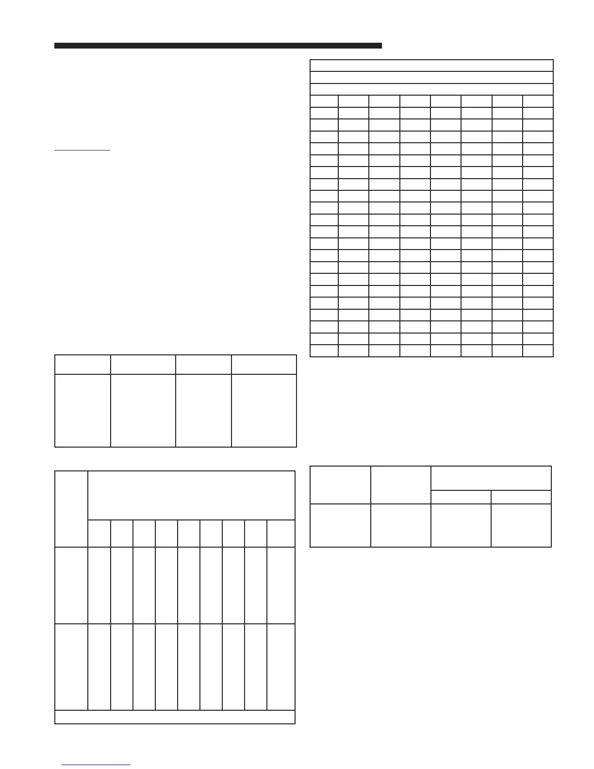
Orifice
Twist
Drill
Size If
In-
stalled
At Sea
Level
ALTITUDE ABOVE SEA LEVEL
and Orifice Required At Other Elevations
2000 3000 4000 5000 6000 7000 8000 9000 10000
42
43
44
45
46
47
48
49
42
44
45
46
47
48
49
50
43
44
45
47
47
48
49
50
43
44
45
47
47
49
49
50
43
45
46
47
48
49
50
51
44
45
47
48
48
49
50
51
44
46
47
48
49
50
50
51
45
47
48
49
49
50
51
52
46
47
48
49
50
51
51
52
47
48
50
50
51
52
52
52
50
51
52
53
54
55
56
57
58
51
51
52
54
54
55
56
58
59
51
52
53
54
55
55
56
59
60
51
52
53
54
55
55
57
59
60
51
52
53
54
55
56
57
60
61
52
52
53
54
55
56
57
60
62
52
53
53
54
55
56
58
61
62
52
53
54
55
56
56
59
62
63
53
53
54
55
56
56
59
63
63
53
54
54
55
56
57
60
63
64
From National Fuel Gas Code - Table F-4
TABLE 17
Note:
Natural gas input rate should be clocked at gas meter in high
heat when the gas valve is replaced or gas valve pressure
adjustments are made.
Table 19 lists the main burner orifices used with the Furnace.
Note:
The LP Conversion Kit used with the modulating furnace
is BAYLPSS220B or BAYLPKT220B.
Table 19 ORIFICE SIZES
INPUT
RATING
BTUH
NUMBER
OF
BURNERS
MAIN BURNER ORIFICE
DRILL SIZE
NAT. GAS LP GAS
60,000
80,000
100,000
120,000
3
4
5
6
45
45
45
45
56
56
56
56
TABLE 18
GAS FLOW IN CUBIC FEET PER HOUR
2 CUBIC FOOT DIAL
SEC. FLOW SEC. FLOW SEC. FLOW SEC. FLOW
8 900 29 248 50 144 82 88
9 800 30 240 51 141 84 86
10 720 31 232 52 138 86 84
11 655 32 225 53 136 88 82
12 600 33 218 54 133 90 80
13 555 34 212 55 131 92 78
14 514 35 206 56 129 94 76
15 480 36 200 57 126 96 75
16 450 37 195 58 124 98 73
17 424 38 189 59 122 100 72
18 400 39 185 60 120 104 69
19 379 40 180 62 116 108 67
20 360 41 176 64 112 112 64
21 343 42 172 66 109 116 62
22 327 43 167 68 106 120 60
23 313 44 164 70 103 124 58
24 300 45 160 72 100 128 56
25 288 46 157 74 97 132 54
26 277 47 153 76 95 136 53
27 267 48 150 78 92 140 51
28 257 49 147 80 90 144 50
If the desired input rate cannot be achieved with a
change in manifold pressure, then the orifices must be
changed. See Table 16 for replacement orifice part num-
bers.
LP installations will require an orifice and gas valve
change. Order kit BAYLPKT220B or BAYLPSS220B.
IMPORTANT:
Reinstall the propane orifices to the same depth as the ori-
fices supplied with the equipment.
See Table 17 for help in selecting orifices if orifice
change is required. Furnace input rate and temperature
rise should be checked again after changing orifices to
confirm the proper rate for the altitude. The vent length
table on page 19 shows the required vent lengths
for installations at various altitudes. An optional high
altitude kit is available for installations above 4000 feet
(Installations above 12,000 feet are not allowed). Use
Table 15A to select the appropriate high altitude kit for
your furnace model.
TABLE 16
PART NUMBERS FOR REPLACEMENT ORIFICES
DRILL
SIZE
PART
NUMBER
DRILL
SIZE
PART
NUMBER
44
45
46
47
48
49
50
51
ORF00501
ORF01427
ORF00909
ORF01429
ORF01099
ORF00503
ORF00493
ORF00494
52
53
54
55
56
57
58
59
ORF00495
ORF00504
ORF00555
ORF00693
ORF01428
ORF00908
ORF01338
ORF01339