Do you have a question about the Trane VAV and is the answer not in the manual?
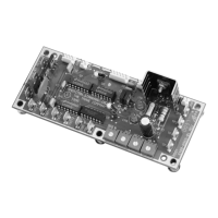
Details the Unit Control Module (UCM) 4.2 Retrofit Model VAV.
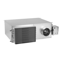
Specifies the VAV models for which this retrofit kit is designed.
Highlights potential hazards (WARNING, CAUTION) and safety practices.
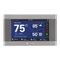
Provides purpose, scope, and functional details of the DDC/VAV retrofit kit.
Details the types of HVAC units and systems compatible with the retrofit kit.
Outlines the available basic kits for the UCM 4.2 retrofit.
Key benefits and features of the Honeywell actuator.
Key benefits and features of the Belimo actuator.
Description of the UCM and Delta P transducer assembly.
Mandatory safety warnings for electrical and mechanical hazards during installation.
Steps and checks needed before commencing the retrofit kit installation.
Instructions for mounting the controller in a vertical plane.
Steps for installing the actuator and setting damper rotation.
Illustrates the wiring connections for the UCM 4.2 control system.
Provides a chart correlating sensor signal with airflow delivery.
| Category | Control Unit |
|---|---|
| Input Voltage | 24 VAC |
| Type | Variable Air Volume (VAV) |
| Communication Protocol | BACnet MS/TP |
| Operating Temperature | 32°F to 122°F (0°C to 50°C) |