WSHP-SVX04A-EN 19
Low Voltage Wiring for Field
Provided Thermostats/Zone
Sensors
Ensure that the AC control wiring be-
tween the controls and the unit’s ter-
mination point does not exceed three
(3) ohms/conductor for the length of
the run.
Note: Resistance in excess of 3-ohms
per conductor may cause component
failure due to insufficient AC voltage
supply.
Check all loads and conductors for
grounds, shorts, and mis-wiring.
Use copper conductors unless other-
wise specified.
Do not run the AC low voltage wiring
in the same conduit with the high volt-
age power wiring.
Table 3: 24V AC conductors
Distance
from unit to Control
Recommended
Wire Size
000-460 feet 18 gauge
461-732 feet 16 gauge
733-1000 feet 14 gauge
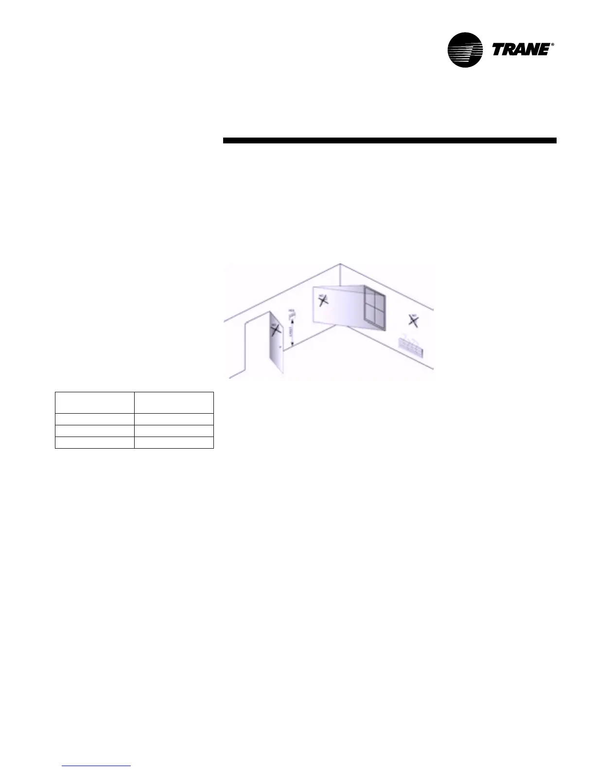
Thermostat Location
Location of the room thermostat/zone sensor cis an important element of effec-
tive room control.
Areas where the thermostat or zone sensor should not be located include : be-
hind doors, or corners; Near hot or cold air ducts; Near radiant heat (heat emitted
from appliances or the sun); Near concealed pipes or chimneys; On outside walls
or other non conditioned surfaces; In airflows from adjacent zones or other units
(Figure 7).
Installation
Low Voltage Wiring
Figure 7: Thermostat/sensor location