Do you have a question about the Trane X13790901030 and is the answer not in the manual?
Refers to installation, operation, and maintenance guide for Air-Fi® Wireless.
Refers to network design best practices guide for Air-Fi® Wireless.
Explains the color coding for WCI wiring connections.
Warns about hazardous voltage and lockout/tagout procedures.
Details WCI wiring to the IntelliPak/CSC controller.
Details WCI wiring to ReliaTel controllers.
Explains WCI wiring for Tracer SC/SC+ with IMC power budget.
Details WCI wiring as a repeater with Tracer SC+.
Provides the recommended order for powering on devices.
Describes how to identify the network coordinator when a Tracer SC is present.
Explains manual network formation when no Tracer SC is present.
The NWK LED illuminates on every WCI that joins the network.
Network automatically stays open for 1 hour; timer resets with each WCI join.
Interprets the Network LED (green) status for WCI network participation.
Interprets the Coordinator LED (yellow) status for WCI network role.
Interprets the Open Net LED (yellow) status for network availability.
Interprets the Reception LED (yellow) status for data reception.
Interprets the Transmission LED (green) status for data transmission.
Interprets the Diagnostic LED (red) status for hardware/communication issues.
Interprets the Power LED (green) status for device power.
Lists minimum firmware levels required for devices to participate in an Air-Fi® Wireless network.
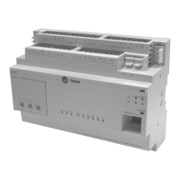
The Trane Air-Fi® Wireless Communications Interface (WCI) is a crucial component in Trane's Air-Fi® wireless network, designed to facilitate communication between various HVAC system controllers and the network. It acts as a bridge, enabling wireless connectivity for devices that might otherwise require wired connections, thereby simplifying installation and offering greater flexibility in system layout.
The WCI serves multiple roles within the Air-Fi® wireless network:
In summary, the Trane Air-Fi® Wireless Communications Interface is a versatile and integral component of Trane's wireless HVAC control systems, offering flexible installation, robust communication, and clear diagnostic capabilities through its LED indicators. Its ability to act as a coordinator, standard interface, or repeater makes it adaptable to various system sizes and complexities, while its integration with Tracer SC/SC+ controllers provides a comprehensive solution for building management.
| Brand | Trane |
|---|---|
| Model | X13790901030 |
| Category | Recording Equipment |
| Language | English |