User's Information
Regular Dealer Maintenance
ELECTRIC SHOCK HAZARD. To prevent injury or death due
to electrical shock or contact with moving parts. Lock unit
disconnect switch in open position before servicing unit.
Cooling Season
To keep your unit operating safely and efficiently, a qualified
service technician should check the entire system seasonally,
and any other time that you feel a check is needed. Your
service technician may examine these areas of the unit:
1. filters (for possible cleaning)
2. motors (condenser and evaporator motors are perma-
nently lubricated)
3. gaskets (for possible replacement)
4. refrigerant coils (for possible cleaning)
5. safety controls (for mechanical cleaning)
6. electrical components and wiring (for possible replace-
ment and connection tightness)
7. condensate drain (for possible cleaning)
8. inspect the unit duet connections to see that they are
physically sound and sealed to the unit casing.
9. inspect the unit mounting support to see that it is sound.
10.inspect the unit to see that there is no obvious unit
deterioration.
Heating Season
At the beginning of each heating season complete the unit
inspections and service routines described in this section.
These steps should be performed ONLY by a qualified service
technician.
1. Inspect the control panel wiring and heating controls to
make sure connections are tight and wiring insulation is
intact.
2. Cheek the operation of the gas ignition system.
a. Turn the unit on and off at the thermostat to be sure
the ignition control and spark electrode are operating.
b. Turn off the gas supply with the unit operating to
verify that the gas valve closes and that a re-ignition
cycle is initiated by the ignition control.
3. Check the burner manifold pressure. A pressure tap is
provided in the gas valve for this purpose.
4. Visually inspect all of the unit's flue product passageways
for excessive deposit buildup or corrosion. If buildup or
corrosion is apparent, perform the necessary repairs.
5. Arrange for a qualified service technician to inspect the
unit every heating season to maintain safe and efficient
operation.
6. Visually check the main burner flames. They should be
bright blue flames extending up to the heat exchanger
sections.
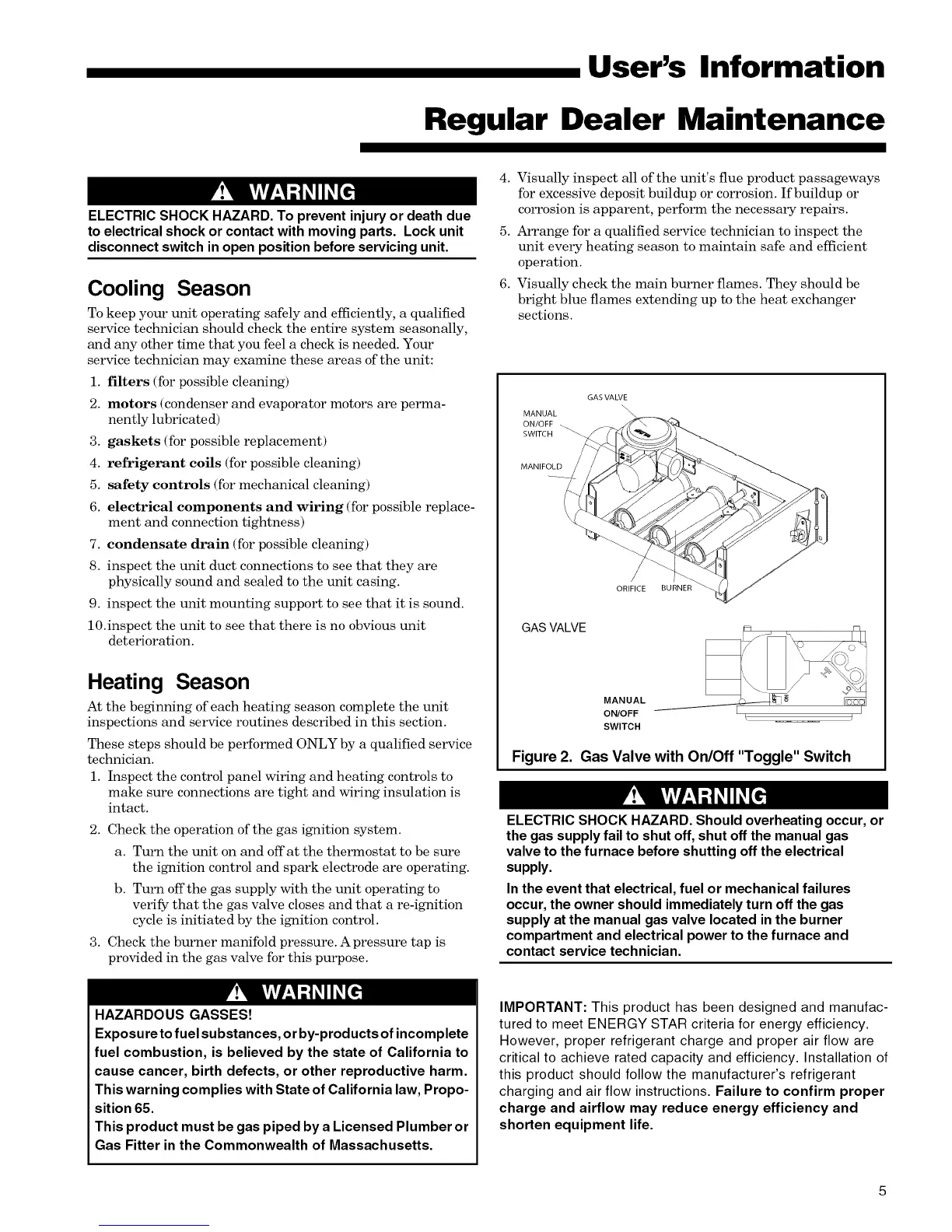
GAS VALVE
\\
MANUAL \\
ON/OFF __
SWITCH
MANIFOLD
ORIFICE BURNER
GAS VALVE
MANUAL
ON/OFF
SWITCH
R M
=k._/ ::
k
Figure 2. Gas Valve with On/Off "Toggle" Switch
ELECTRIC SHOCK HAZARD. Should overheating occur, or
the gas supply fail to shut off, shut off the manual gas
valve to the furnace before shutting off the electrical
supply.
In the event that electrical, fuel or mechanical failures
occur, the owner should immediately turn off the gas
supply at the manual gas valve located in the burner
compartment and electrical power to the furnace and
contact service technician.
V!'WkViVl-'!d
HAZARDOUS GASSES!
Exposure to fuel substances, or by-products of incomplete
fuel combustion, is believed by the state of California to
cause cancer, birth defects, or other reproductive harm.
This warning complies with State of California law, Propo-
sition 65.
This product must be gas piped by a Licensed Plumber or
Gas Fitter in the Commonwealth of Massachusetts.
IMPORTANT: This product has been designed and manufac-
tured to meet ENERGY STAR criteria for energy efficiency.
However, proper refrigerant charge and proper air flow are
critical to achieve rated capacity and efficiency. Installation of
this product should follow the manufacturer's refrigerant
charging and air flow instructions. Failure to confirm proper
charge and airflow may reduce energy efficiency and
shorten equipment life.
 Loading...