2
24-Hour Technical Support: 1-800-260-1312 -- International: 00-1-952-941-7600
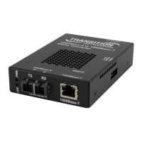
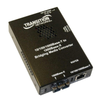
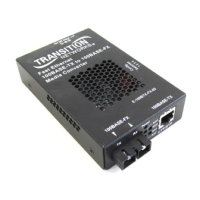
SSDTF10xx-10x
(TX) = transmit (RX) = receive
* Typical maximum cable distance. Actual distance is dependent upon the physical
characteristics of the network.
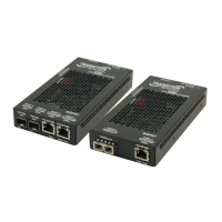
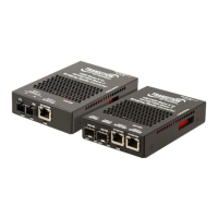
** SSDTF1029-105 and -106 are intended to be installed in the same network where
one is the local converter and the other is the remote converter.
*** SSDTF1029-107 and -108 are intended to be installed in the same network where
one is the local converter and the other is the remote converter.
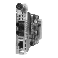
Note: The chassis version of the media converter is CSDTF10xx-10x. For more
information, see the CSDTF10xx-10x user’s guide on-line at: www.transition.com
Optional Accessories (sold separately)
Part Number Port One - Copper Port Two - Single Fiber Optic
SSDTF1029-105 **
RJ-45
1.5 km (5,000 feet)*
SC, 1310 mn (TX)/1550 nm (RX)
single mode, 20 km (12.4 miles)*
SSDTF1029-106 **
RJ-45
1.5 km (5,000 feet)*
SC, 1550 mn (TX)/1310 nm (RX)
single mode, 20 km (12.4 miles)*
SSDTF1029-107 ***
RJ-45
1.5 km (5,000 feet)*
SC, 1310 mn (TX)/1550 nm (RX)
single mode, 40 km (24.8 miles)*
SSDTF1029-108 ***
RJ-45
1.5 km (5,000 feet)*
SC, 1550 mn (TX)/1310 nm (RX)
single mode, 40 km (24.8 miles)*
Part Number Description
SPS-1872-SA
Optional External Power Supply; 18-72VDC Stand-Alone
Output: 12.6VDC, 1.0 A
SPS-1872-PS
Optional External Power Supply; 18-72VDC Piggy-back;
Output: 12.6VDC, 1.0 A
E-MCR-04
12-Slot media converter Rack (includes universal internal power
supply) 17 x 15 x 5 in. (432 x 381 x 127 mm)
WMBL
Optional Wall Mount Brackets
Length: 4.0 in. (102 mm), Fits converter length: 4.7 in. (119 mm)
WMBV
Optional Vertical Mount Bracket; 5.0 in. (127 mm)
WMBD
Optional DIN Rail Mount Bracket; 5.0 in. (127 mm)
WMBD-F
Optional DIN Rail Mount Bracket (flat); 3.3in. (84 mm)
techsupport@transition.com -- Click the “Transition Now” link for a live Web chat.
3
Installation
CAUTION: Wear a grounding device and observe electrostatic discharge precautions
when setting the jumper and switches. Failure to observe this caution could result in
damage to, and subsequent failure of, the media converter.
Set the hardware/software jumper
The hardware/software jumper is located on the circuit board inside the media
converter housing.
Hardware: The media converter mode is determined
by the switch settings.
Software: The media converter mode is determined
by the most-recently saved, on-board
microprocessor settings.
To set the two-position jumper:
1. Using a small screwdriver, remove the four (4) screws that secure the cover and
carefully remove the cover from the media converter.
2. The jumper is located on the circuit board and is labeled “H” and “S”.
3. Using small needle-nosed pliers or similar device, move the jumper to the
desired position. (Refer to the above drawing.)
4. Carefully replace the cover on the media converter and replace the four (4)
screws that secure the cover to the media converter.
Set the MDI/MDI-X switch (hardware mode only)
The MDI/MDI-X switch is located on the side of the media converter. This switch
allows the network administrator to use straight-through cable in installations where
crossover configuration cable is required. Use a small flat-blade screwdriver or a
similar device to set the recessed switch.
Set the switch to MDI if using
straight-through copper cable to
connect two unlike devices.
Set the switch to MDI-X if using
crossover copper cable to connect
two like devices.
 Loading...