
A
Annette BergAug 4, 2025
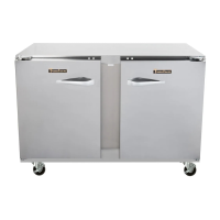
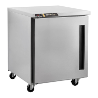
Why is the food compartment in my Traulsen centerline CLUC-27R-SD too warm?
- RRichard JensenAug 4, 2025
If the food compartment of your Traulsen Refrigerator is too warm, there might be an improper seal on the doors and gaskets. Check the door(s) and gasket(s) to ensure they are properly sealed. Also, if a large quantity of warm food was recently added or the door was left open, allow adequate time for the cabinet to return to its normal operating temperature. Ensure that the condensing coil is clean. If the control setting is too high, readjust it.