Do you have a question about the Traxxas SLASH 58014-4 and is the answer not in the manual?
Details critical safety warnings and precautions specific to the handling and use of Lithium Polymer (LiPo) batteries.
Provides essential safety guidelines for charging and handling all types of batteries, emphasizing fire prevention.
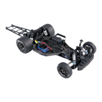
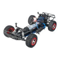
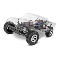
Detailed steps for assembling the front and rear shock absorbers, including filling with oil.
Mounts the pinion gear on the motor and installs the motor into the transmission assembly.
Builds the slipper clutch mechanism and attaches the spur gear to the input shaft.
Installs the assembled rear shock absorbers onto the chassis.
Assembles steering bellcranks and draglink, then attaches to skidplate and bulkhead.
Connects the steering link and servo saver to the steering bellcrank.
Installs the assembled front shock absorbers onto the chassis.
Mounts the steering servo into the Slash chassis.
Installs the electronic speed control (ESC) onto the chassis.
Places the TQ receiver and foam into the lower receiver box.
Routes and connects the servo and ESC wires to the receiver.
Connects the completed rear module assembly to the main chassis.
Mounts the completed front module assembly to the main chassis.
Guides the user through centering the steering servo before final connections.
Attaches the servo horn to the steering servo spline.
Mounts the assembled tires and wheels onto the front and rear axles.
Initial steps to get the model ready for operation, including battery and charger selection.
Guidance on choosing compatible chargers and batteries for optimal performance and safety.
Instructions for correctly installing the battery pack into the model's chassis.
Procedure for powering on the transmitter and the model in the correct sequence.
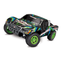
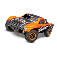
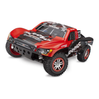
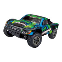
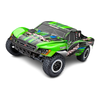
| Scale | 1/10 |
|---|---|
| Suspension | Independent |
| Speed Control Type | Electronic |
| Battery | 7-cell NiMH or 2S LiPo |
| Radio System | TQ 2.4GHz |
| Chassis | Composite |
| Speed Control | XL-5 |
| Wheel Size | 2.2 in |
| Gear Pitch | 48 |
| Transmission | Single speed |
| Top Speed | 30+ mph |
| Motor | Titan® 12T 550 (modified) |
| Steering | Bellcrank |