SUMMIT
•
27
DUAL SERVO STEERING SYSTEM
Summit uses dual-servo steering and a single heavy-duty servo saver for
powerful, responsive steering. To prevent unnecessary receiver battery
drain, it is important to make sure that the servos are “at rest” when the
steering is at neutral. If one servo is out of adjustment, then both servos
will work against each other, fighting to find center.
Adjusting The Steering System
1.
Remove the servo horns and steering links from the servos.
Disconnect the steering links from the servo saver.
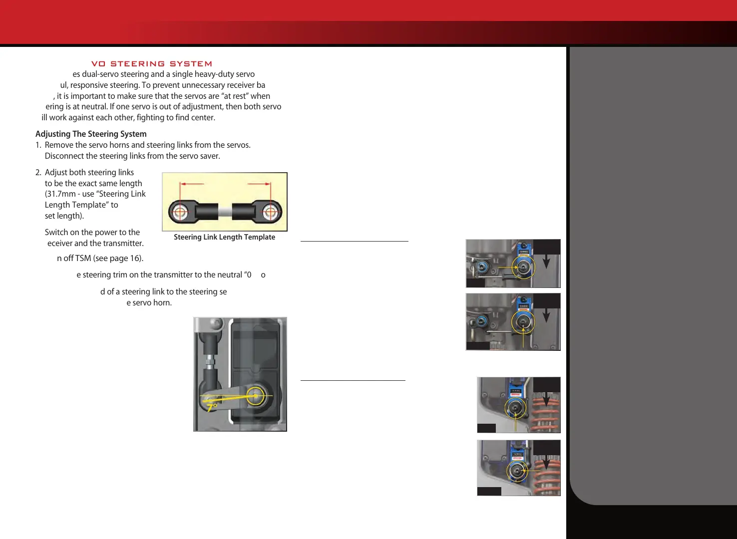
2.
Adjust both steering links
to be the exact same length
(31.7mm - use “Steering Link
Length Template” to
set length).
3.
Switch on the power to the
receiver and the transmitter.
4. Turn off TSM (see page 16).
5. Adjust the steering trim on the transmitter to the neutral “0” position.
6. Connect one end of a steering link to the steering servo saver arm
and the other end to the servo horn.
7.
Position the steering servo saver arm
perpendicular to the centerline of the
vehicle.
8.
While holding the steering servo saver
arm in the position mentioned in step
6, install the servo horn onto the servo
such that the steering link is parallel
with the centerline of the vehicle. This
will automatically set the servo horn at
the 7-degree offset shown in
the illustration.
9.
Install the second servo horn on the other side following the same
procedure.
If necessary, fine-tune the length of the second steering link to
eliminate any load on the steering system in the neutral position. If you
are using aftermarket servos, it is important to use servo horns designed
for Summit. Optional steering servo horns are sold separately for use
with non-Traxxas servos.
T-LOCK SERVO INSTALLATION
The Summit’s T-Lock differential control servos are installed and pre-
set at the factory. If you need to remove the servos or the servo horns
for maintenance or cleaning, carefully note their orientation when you
reinstall them to make certain the T-Lock system operates properly.
Before reinstalling the spring-loaded servo horns, reset the servos’
output shafts to the “diffs open” position.
1. Switch the transmitter and receiver on and plug the T-Lock servos
into their correct positions on the receiver unit (see page 11).
2. Operate the transmitter’s T-Lock switch to make certain both servos
operate properly, then place the switch in the full-up position for
unlocked front and rear diffs (see page 19).
3. Install the servo horns as shown below. Switch the transmitter and
on-board electronics off before completing the installation.
Front Differential T-Lock Servo
Differential Open: Install the spring-loaded
servo horn so the spring slot is parallel to the
linkage and the bellcrank is pushed away from
the servo, as viewed in the photo.
Differential Locked: Switch the transmitter
and receiver on. Move the T-Lock switch to the
middle position to lock the front differential.
Confirm that the servo’s output shaft turns
counterclockwise to rotate the servo horn to the
position shown, with the spring slot perpendicular
to the linkage and the bellcrank pulled toward the servo.
Rear Differential T-Lock Servo
Differential Open: Install the spring-loaded servo
horn so the spring slot is parallel to the linkage
and the bellcrank is pulled toward the servo, as
viewed in the photo.
Differential Locked: Switch the transmitter and
receiver on. Move the T-Lock switch to the bottom
position to lock the rear differential. Confirm that
the servo’s output shaft turns counterclockwise to
rotate the servo horn to the position shown, with
the spring slot perpendicular to the linkage and
the bellcrank pushed away from the servo.
Steering Link Length Template
31.7mm
TUNING ADJUSTMENTS
Front of
Truck
Open
Open
Locked
Locked
Front of
Truck
Front of
Truck
Front of
Truck