Chapter 3: Adjustment25
Brake-levers
A brake lever allows you to control a brake. The
position of the lever on the handlebar should
allow you to use the brake with a minimum
amount of effort or movement.
There are several types of brake levers:
• Road lever: for drop-type handlebar
(Figure 32).
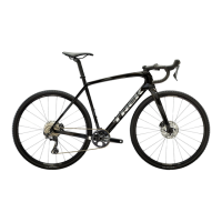
• Mountain lever: for flat or mountain-type
handlebar (Figure 33).
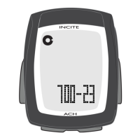
• Middle-bar brake lever: for drop-type
handlebar (Figure 34). This type of lever is
used with a road lever to provide additional
hand positions.
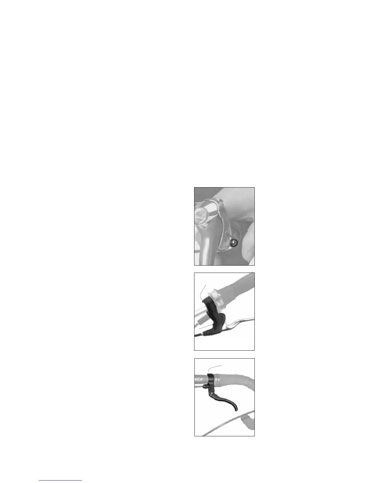
To align a hydraulic disc brake
1. Decrease the tightness of the brake-
attachment bolts (Figure 31).
2. Fully pull the lever, and tighten the bolts to
100-110 lb•in (11.3-12.4 N•m).
To align a cable-actuated disc brake
There are three parts to this procedure:
A. To adjust the clearance between the right
brake-pad and the disc
1. Turn the fixed-pad adjuster (Figure 31).
2. If the pads can not be adjusted correctly
in this manner, follow the instructions “To
adjust the clearance between the left brake-
pad and the disc,” and then adjust the right
pad.
B. To adjust the clearance between the left
brake-pad and the disc
1. Turn the cable barrel-adjuster: clockwise to
increase clearance, counterclockwise to
decrease clearance.
2. If the pads can not be adjusted correctly,
decrease the tightness of the cable-clamp
bolt and re-attach the cable. Tighten the
cable-clamp bolt to 50-70 lb•in (5.7-7.9 N•m).
3. After adjustment, turn the lock-nut clockwise
to make sure the adjustment does not change.
C. To align the brake with the disc
1. Decrease the tightness of the brake-
attachment bolts.
2. Slide a business card or other thin object
between the right brake-pad and the disc.
3. Pull the lever fully, and tighten the bolts to
100-110 lb•in (11.3-12.4 N•m).
To remove disc brake-pads
1. Remove the wheel.
2. With your fingers or pliers, hold the installation
tang of the brake-pad and pull out the pad.
FIGURE 32:
Road lever
1. Lever-clamp bolt
1
FIGURE 34:
Middle-bar brake-lever
1. Lever-clamp bolt
1
FIGURE 33:
Mountain lever
1. Lever-clamp bolt
2. Reach-adjustment
screw
1
2