IQ3xcite Installation Instructions - Mounting TG200626 Issue 4, 29/12/2010 5
Installation Instructions – Mounting IQ3xcite
11
Auxiliary Board Installation
12
Install I/O Modules (IQ3XCITE/96/.. and /128.. only)
3 INSTALLATION (continued)
13
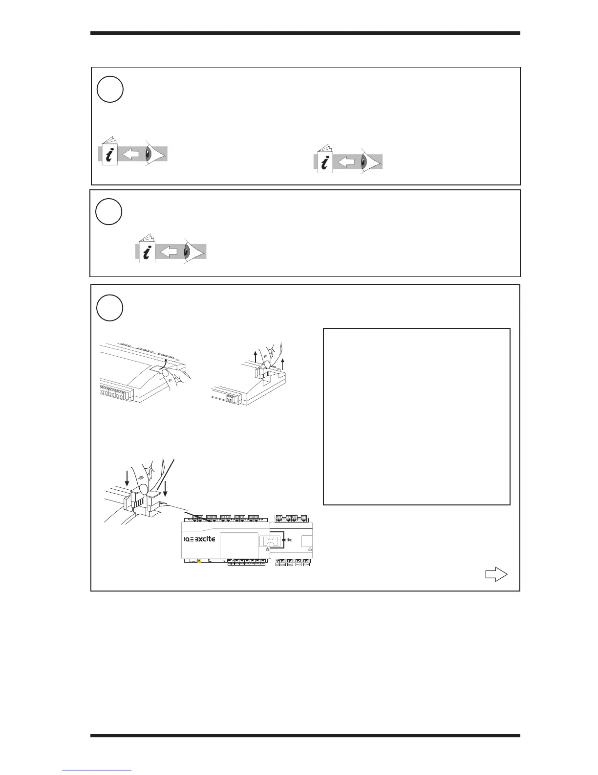
Connect I/O Bus (IQ3XCITE/96/.. and /128.. only)
if auxiliary board already fi tted
(for fi tting and installing battery board, XCITE/BBC, see IQ3 Installation Instructions - Confi guration TG201160,
section 1 step 10). Note that fi tting IQ3/LAN/UGR Lan board upgrade is described in IQ3/LAN/UGR installation
instructions TG201162.
for IQ3../.../XNC/..., including
IQ3../.../LAN/XNC/..., IQ3../.../SER/XNC/...
IQ3../.../XNC/... Installation
Instructions-Mounting, TG200911
section 1
for IQ3../.../LAN/...
IQ3../.../LAN/... Installation
Instructions-Mounting, TG200916
section 1
XCITE Standard I/O Modules Installation Instructions-Mounting
TG200627, section 3 steps 1 to 11 only
if required
Remove Terminator
b
XCITE/IC interconnector (supplied)
(XCITE/IC/5, pack of 5 available separately)
Open Flap
a
• A maximum of 15 I/O modules can be connected.
• A maximum of 96 or 128 points (16 points in the
IQ3xcite and 80 or 112 expansion points) can be
used.
• The controller and its I/O modules are to be fi tted
inside enclosures.
• No spurs are allowed on the I/O bus.
• If a single earth (ground) screened and bonded
contiguous metal enclosure is used, then total
I/O bus length can be up to 30 m (includes use of
multisection panels e.g. Form 4 enclosures)
If any other type of enclosure is used, or I/O bus
runs between enclosures, then total I/O bus cable
length can be up to 10 m.
(For cable length calculation, rigid interconnectors
can be ignored)
• Multiple enclosures must be earthed (grounded)
to a common earth (ground) point (according to
latest IEE Regs).
either use XCITE/IC interconnector (supplied with I/O module)c
 Loading...