Do you have a question about the TREND IQ3xcite and is the answer not in the manual?
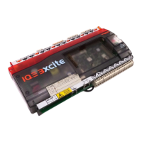
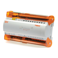
Physical dimensions of the IQ3xcite controller and its mounting features.
Environmental and safety requirements for the IQ3xcite controller installation.
Instructions on how to physically mount the IQ3xcite controller.
Detailed steps for connecting the power supply to the IQ3xcite controller.
Guidance on connecting the IQ3xcite controller to an Ethernet network.
Wiring instructions for connecting input signals to the IQ3xcite controller.
Instructions for segregating screen earth from the power supply earth.
Wiring instructions for connecting output signals from the IQ3xcite controller.
How to connect the output power terminals for specific configurations.
Steps to connect an auxiliary 24V supply if needed.
Instructions for installing auxiliary boards with the IQ3xcite.
Guidance on installing optional I/O modules for the IQ3xcite.
Steps for connecting the I/O bus between modules and the controller.
Instructions on how to properly terminate the I/O bus.
Reference to IQ3 configuration instructions.
| Brand | TREND |
|---|---|
| Model | IQ3xcite |
| Category | Controller |
| Language | English |