4 IQ3xcite Installation Instructions - Mounting TG200626 Issue 4, 29/12/2010
IQ3xcite Installation Instructions – Mounting
8
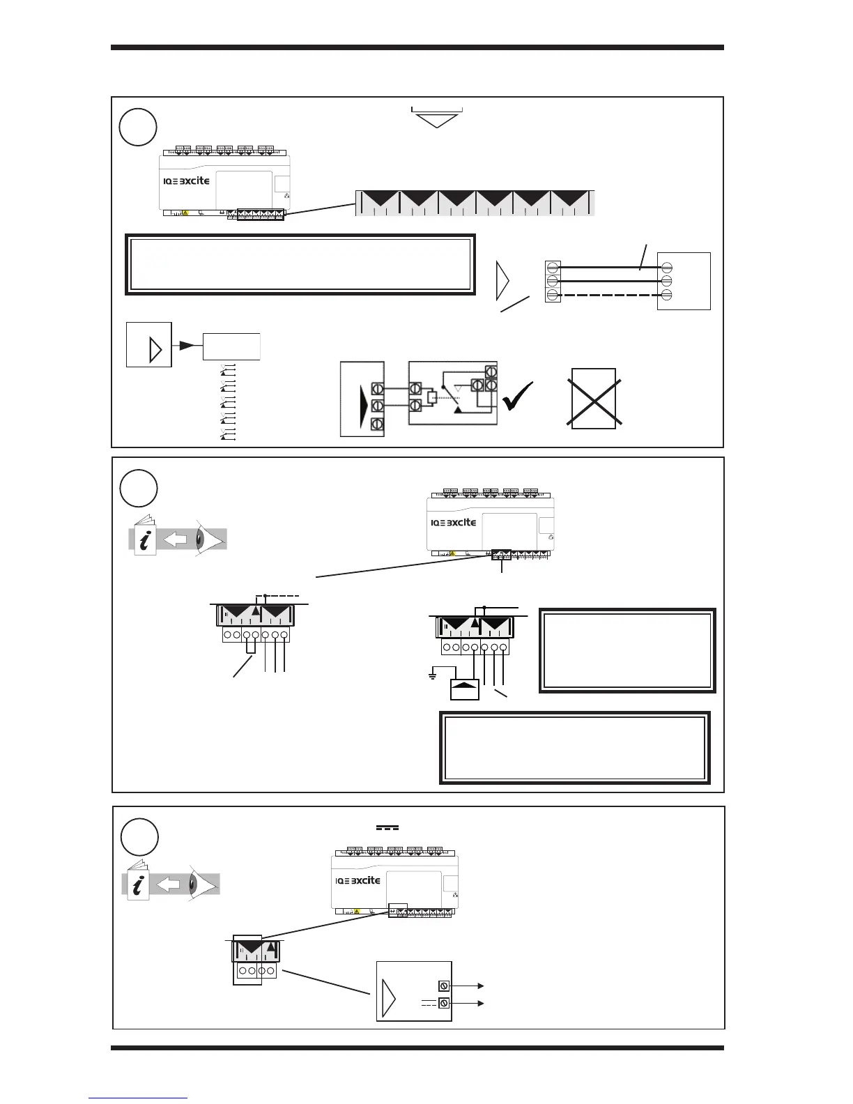
Connect Outputs (channels 11 to 16)
N
4 5 6
2
7 8 9
3
10 11 12
4
13 14 15
5
16 17 18
6
19 20 21
7
22 23 24
8
25 26 27
9
28 29 30
10
+ 0
+ 0
+ 0
+ 0 + 0 + 0
+ 0
+ 0
+ 0
1 2 3
1
+ 0
0 V
24 V
24 V
34 35 36
12
37 38 39
13
40 41 42
14A
31 32 33
P
11
43 44 45
15
46 47 48
16
100-240 V
OK RX
P 0
P 0
P 0
P 0
P 0
P 0
34 35 36
12
37 38 39
13
40 41 42
14
31 32 33
11
43 44 45
15
46 47 48
16
P 0
P 0
P 0
P 0
P 0
P 0
IQ3
Relay
Module
SRMV =
x 1
2SRM =
x 2
3RM =
x 3
6RM =
x 6
2RM =
x 2
nRM
N
Additional Relay Modules
(R/L, H/L)
(HCM/TRM)
Cable size 0.5 to 2.5 mm
2
(14 to 20 AWG) - Cu only
0
(out) N
P
N
LOAD
(0 V)
(+24 V)
optional
(0 to 10 Vdc, <=20 mA)
If P terminal used, P input terminal must
be connected as in step 9 below
I<=20 mA
TP/1/1/22/HF/200 (Belden 8761) cable recommended for voltage outputs
EN61010:2001 MEASUREMENT CATEGORY 1. Separate from 230 Vac input power supply
by double or reinforced insulation
If screened cable is used, terminate screen to earth (ground) at one end
WARNING
If external supply is used to supply P input terminal, note whether
P bus is 24 Vac or 24 Vdc and only connect appropriate output
devices to P output terminals
e.g.
IQ3
SRMV
P
0
SRMAC
Analogue
outputs are
not suitable
for ac relays
9
Connect Output Power (P)
3 INSTALLATION (continued)
either use IQ3 24 Vdc auxiliary supply
4 5 6
2
7 8 9
3
10 11 12
4
13 14 15
5
16 17 18
6
19 20 21
7
22 23 24
8
25 26 27
9
28 29 30
10
+ 0
+ 0
+ 0
+ 0 + 0 + 0
+ 0
+ 0
+ 0
1 2 3
1
+ 0
0 V
24 V
24 V
34 35 36
12
37 38 39
13
40 41 42
14A
31 32 33
P
11
43 44 45
15
46 47 48
16
100-240 V
OK RX
P 0
P 0
P 0
P 0
P 0
P 0
or use 24 Vdc or 24 Vac external supply
A
0 V
24 V
24 V
A
31 32 33
P
11
P 0
Fit external link
if P terminal used (see step 8 above)
Check IQ3 24 Vdc combined and
auxiliary output current availability:
IQ3 Confi guration Manual TE200768
A
PSU
0V
24 V
24 V
A
31 32 33
P
11
P 0
External PSU
WARNING
External PSU must be dedicated to
I/O channel use, and comply with
relevant EMC and safety standards
WARNING
If external supply is used, note whether P bus is 24 Vac
or 24 Vdc and only connect appropriate output devices
to P output terminals
EN61010:2001
MEASUREMENT CATEGORY 1
Separate from 230 Vac input
power supply by double or
reinforced insulation
Connect external supply (no external link)
terminal size 0.5 to 2.5 mm
2
(14 to 20 AWG)
10
Connect Auxiliary Supply (24 V ) if required
4 5 6
2
7 8 9
3
10 11 12
4
13 14 15
5
16 17 18
6
19 20 21
7
22 23 24
8
25 26 27
9
28 29 30
10
+ 0
+ 0
+ 0
+ 0 + 0 + 0
+ 0
+ 0
+ 0
1 2 3
1
+ 0
0 V
24 V
24 V
34 35 36
12
37 38 39
13
40 41 42
14A
31 32 33
P
11
43 44 45
15
46 47 48
16
100-240 V
OK RX
P 0
P 0
P 0
P 0
P 0
P 0
A
0 V
24 V
24 V
A
P
terminal size 0.5 to 2.5 mm
2
(14 to 20 AWG)
Imax = 150 mA(including current to P bus,
- see step 9 above)
Check IQ3 24 Vdc
combined and
auxiliary output
current availability:
IQ3 Data Sheet
TA200505
Note that the 24 Vdc supply is normally about 22 V
and drops to about 20.7 V at full load.
EN61010:2001 MEASUREMENT CATEGORY 1
Separate from 230 Vac input power supply by double
or reinforced insulation
 Loading...