IQ3xcite Installation Instructions - Mounting TG200626 Issue 4, 29/12/2010 3
Installation Instructions – Mounting IQ3xcite
6
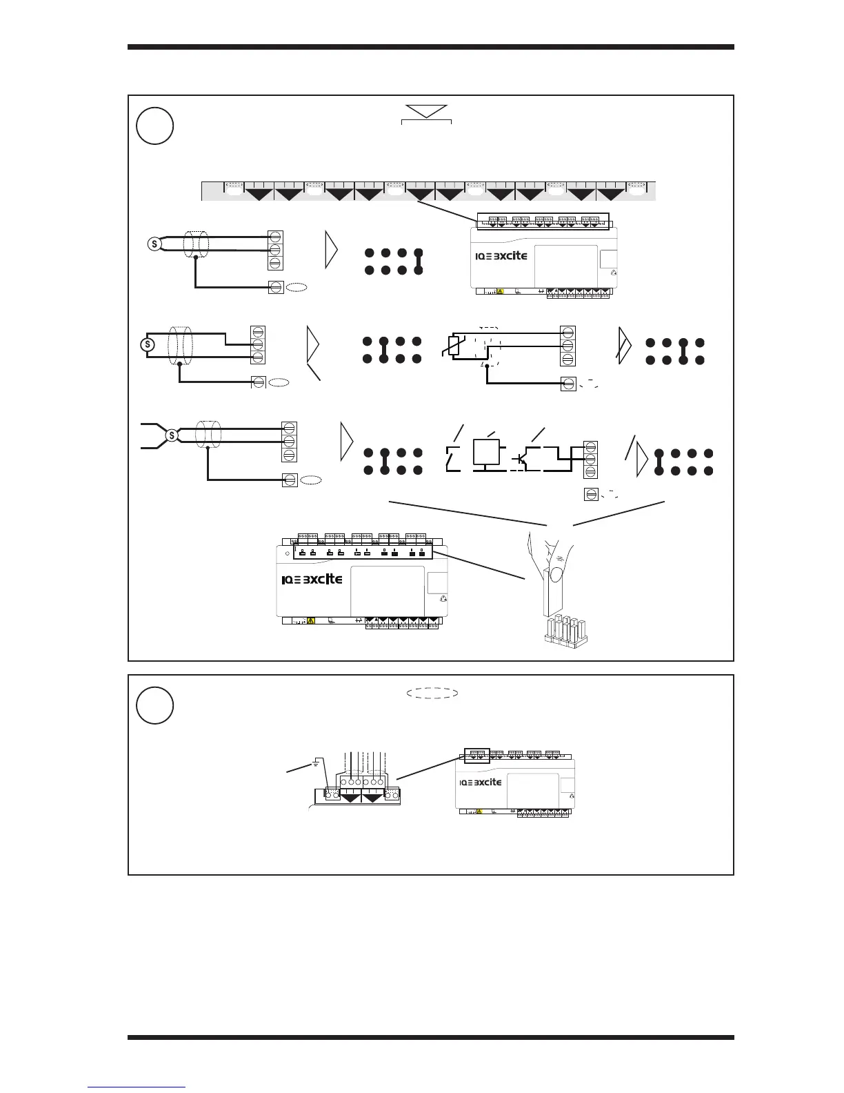
Connect Inputs (channels 1 to 6)
7
Segregate Screen Earth (Ground)
4 5 6
2
7 8 9
3
10 11 12
4
13 14 15
5
16 17 18
6
19 20 21
7
22 23 24
8
25 26 27
9
28 29 30
10
+ 0
+ 0
+ 0
+ 0 + 0 + 0
+ 0
+ 0
+ 0
1 2 3
1
+ 0
0 V
24 V
24 V
34 35 36
12
37 38 39
13
40 41 42
14A
31 32 33
P
11
43 44 45
15
46 47 48
16
100-240 V
OK RX
P 0
P 0
P 0
P 0
P 0
P 0
4 5 6
2
7 8 9
3
10 11 12
4
13 14 15
5
16 17 18
6
19 20 21
7
22 23 24
8
25 26 27
9
28 29 30
10
+ 0
+ 0
+ 0
+ 0 + 0 + 0
+ 0
+ 0
+ 0
1 2 3
1
+ 0
0 V
0 (0 V)
N (in)
+ (+24V)
N
e.g
TTL
CMOS
0 V
Current input (external powered)
linking
(0 to 10V)
0 (0 V)
N (in)
+ (+24V)
N
Voltage input
Current input (loop powered)
®
1
(0 to 20 mA)
0 (0 V)
N (in)
+ (+24V)
N
®
1
(0 to 20 mA)
0V
SIG
0 (0 V)
N (in)
+ (+24V)
N
linking
linking
Digital input
linking
V
I
I
D
Note that setting
input links is
described in
IQ3 Installation
Instructions -
Confi guration
TG201160, section 1
step 7
EN61010:2001 MEASUREMENT CATEGORY 1. Separate from 230 Vac input power supply by double or reinforced insulation.
TP/1/1/22/HF/200 (Belden 8761) cable recommended for all inputs. Cable size 0.5 to 2.5 mm
2
(14 to 20 AWG) - Cu only.
(20 to 36 V)
5 V supply
Thermistor input
0V
0 (0 V)
N (in)
+ (+24V)
N
linking
T
5 V bridge supply
volt free contact
logic
open collector
if required to segregate screen earth (ground) from controller input power supply earth (ground)
3 INSTALLATION (continued)
SERVICE
0V
24 V
24 V
34 35 36
12
37 38 39
13
40 41 42
14
A
31 32 33
P
11
43 44 45
15
46 47 48
16
100-240 V
OK RX
P 0P 0
P 0
P 0
P 0
P 0P 0
P 0
4 5 6
2
7 8 9
3
10 11 12
4
13 14 15
5
16 17 18
6
19 20 21
7
22 23 24
8
25 26 27
9
28 29 30
10
+ 0
+ 0
+ 0
+ 0 + 0 + 0
+ 0
+ 0
+ 0
1 2 3
1
+ 0
0 V
24 V
24 V
34 35 36
12
37 38 39
13
40 41 42
14A
31 32 33
P
11
43 44 45
15
46 47 48
16
100-240 V
OK RX
P 0
P 0
P 0
P 0
P 0
P 0
Note that screen earth (ground) link must be cut (see IQ3 Installation Instructions - Confi guration TG201160, section 1 step 8)
separate
earth (ground)
connection
 Loading...