4 VSD2H Variable Speed Drives Data Sheet TA201104 Issue 3, 08-Oct-2013
VSD2H Data Sheet
Terminal Signal Information Factory Setting
21 RO1/1 Relay out put 1 Nor mally Closed
Switching capacity: 24 Vdc/8 A
250 Vac/8A
125 Vdc/0.4 A
Min. switching load
RUN (active)22 RO1/2 Relay output 1 Common
23 RO1/3 Relay output 1 Normally Open
24 RO2/1 Relay out put 2 Nor mally Closed
Switching capacity: 24 Vdc/8 A
250 Vac/8A
125 Vdc/0.4 A
Min. switching load
FAULT (active)25 RO2/1 Relay output 2 Common
26 RO2/1 Relay output 2 Normally Open
28 TI1+
Thermistor input
R
TRIP
= 4k7 ohms,
Measuring voltage = 3.5 V
Motor temperature
trip thermistor (PTC).
If thermsisor circuit
is not used it must
be short-circuited
29 TI1-
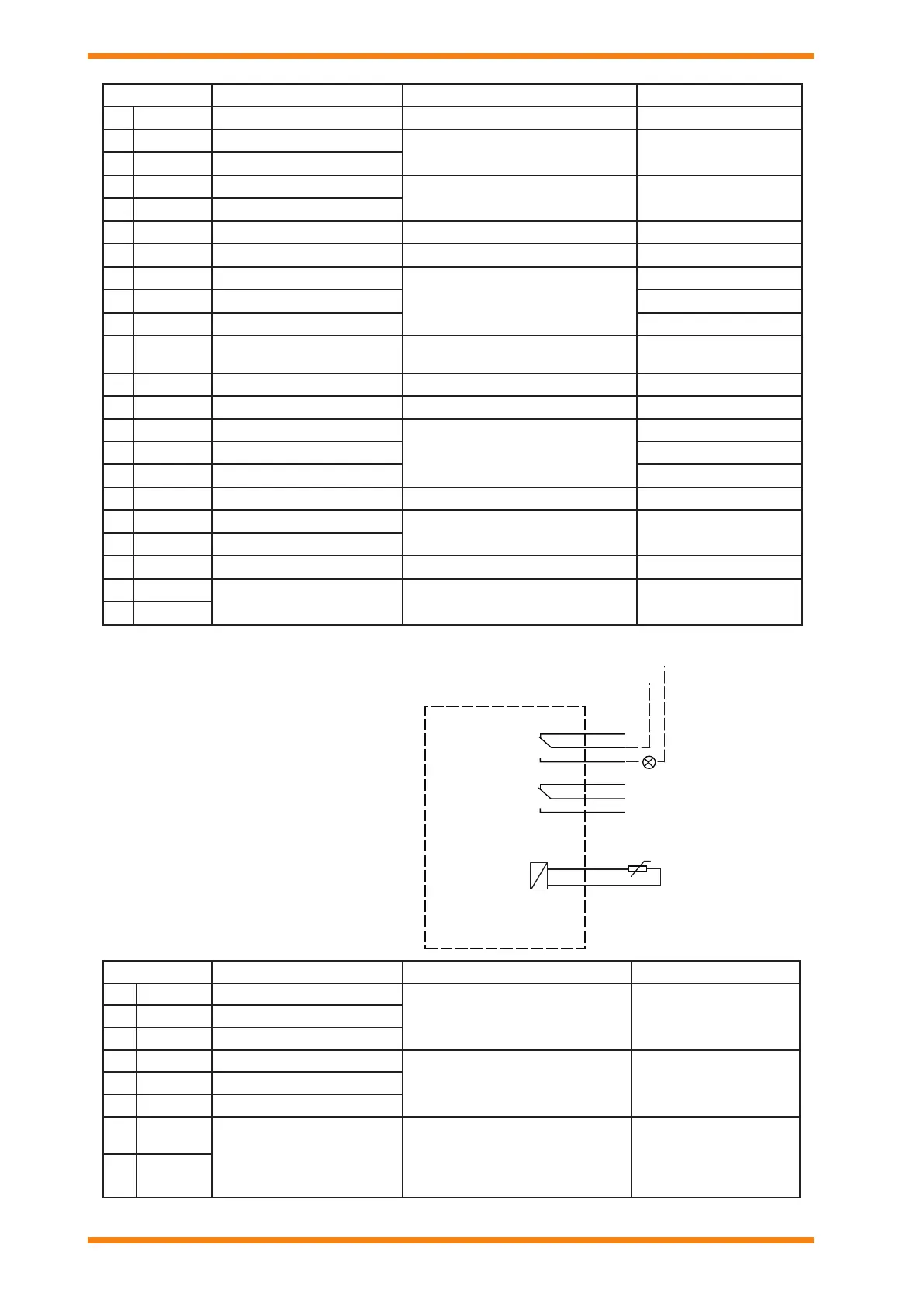
The Basic Relay Board (tted as standard) has:
2 changeover relay output channels
1 thermistor input channel
+t
21
22
23
25
26
Relay board
RO1/1
RO1/2
RO1/3
RO2/2
RO2/3
28
29
TI1+
TI1-
21
RO2/1
from I/O board terminal 13
from I/O board terminal 12
Example: RUN light
Example: Motor temperature
trip thermistor
RUN
GND
24Vout
Terminal Signal Information Factory Setting
1 10 Vref +10 Vdc Reference voltage 10 mA max.
2 AI1+ Analogue input 1 voltage or current
DIP switch 4 selects V or mA.
Differential input if not connected to ground
Speed Reference, 0 to !0 V
3 AI1- Analogue input 1 common
4 AI2+ Analogue input voltage or current
DIP switch 3 selects V or mA.
Differential input if not connected to ground
PID actual value 1, 4 to 20 mA
5 AI2- Analogue input c2 ommon
6 24 Vout 24 V auxiliary voltage output ±10 %, 250 mA max.
7 GND I/O ground Ground for reference and controls
8 DI1 Digital input 1
Rin= 5 kohm min.
0 to 5 V =’0’
15 to 30 V =’1’
Start Forward
9 DI2 Digital input 2 No function
10 DI3 Digital input 3 External fault
11 COM Digital input common
Common for DI1 to 6. Can be disconnected
from ground by removing link
12 24 Vout 24 V auxiliary voltage output as terminal 6
13 GND I/O ground as terminal 7
14 DI4 Digital input 4
Rin= 5 kohm min.
0 to 5 V =’0’
15 to 30 V =’1’
Preset speed select B0
15 DI5 Digital input 5 Preset speed select B1
16 DI6 Digital input 6 Fault Reset
17 COM Digital input common as terminal 11
18 AO1+ Analogue signal (+output)
DIP switch 2 selects V (0 to 10V) or I (0 to
20 mA)
Output frequency, 0 to 20 mA
19 AO1- Analogue output common
30 +24 Vin 24 Vdc auxilary input +24 Vdc, 100 mA , ±10% for backup power*
A RS485 A (+)
Fieldbus communication
Differential receiver/transmitter;
Use for BACnet MS/TP, or MODBUS RTU
B RS485 A (-)
*The control board can be powered externally by
connecting an external power source to terminal 30.
This voltage is sufcient for parameter setting and for
keeping the control unit active. Note however that the
measurements of the main circuit (e.g. DC-link voltage,
unit temperature) are not available when the mains is not
connected.
 Loading...