VSD2H Variable Speed Drives Data Sheet TA201104 Issue 3, 08-Oct-2013 5
Data Sheet VSD2H
Trend Network Interfaces: An optional system network interface can be tted into the VSD2H drive. It is plugged into slot D, and
enables the unit to be monitored and controlled from Trend supervisors (using Text comms), and from Trend IQ controllers (using IC
comms). There are the IQ system current loop Lan interface, NXNI (which provides a standard four wide current loop Lan terminal
set), and the Ethernet interface, NXIP. See NXNI data sheet TA200544 or NXIP data sheet TA200826 for details. Note that the NXNI
allows the unit to be monitored by all Trend IQ controllers, but it can only be written to by IQ3, IQ4. or IQeco controllers.
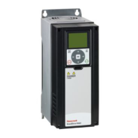
DIP Switch
The 4 DIP switches have 3 functional positions, left, middle, and right. The middle position is used for test mode. The switches are
used to set the folowing parameters:
Switch 1: RS485 eldbus Terminator resistor, on or off (default off)
Switch 2: Analogue Output 1, current or voltage (default current)
Switch 3: Analogue Input 2, current or voltage (default current)
Switch 4: Analogue Input 1, current or voltage (default voltage)
Control Keypad: The control keypad can be used for setting the frequency converter’s parameters, reading status data, and giving
control commands. It is detachable and can be operated externally being connected via a cable to the main unit. There are two
accessory kits available:
ACC/VSD2H/HAND HELD KIT: This enables the keypad to be detached from the unit and to be used as a hand held unit
connected to the VSD by a 2 m cable.
ACC/VSD2H/DOOR MOUNTING KIT: This enables the keypad to be detached from the unit and to be mounted in the panel
door connected to the VSD by a 2 m cable.
RS485
AO1
AI2
AI1
OFFON
Current
RS485 fieldbus termination resistor
Current
Current
Voltage
Voltage
Voltage
Default positions areshown
DIPSwitches
Switch 1
Switch 2
Switch 3
Switch 4
OK
STOP START
BACK
RESET
LOC
REM
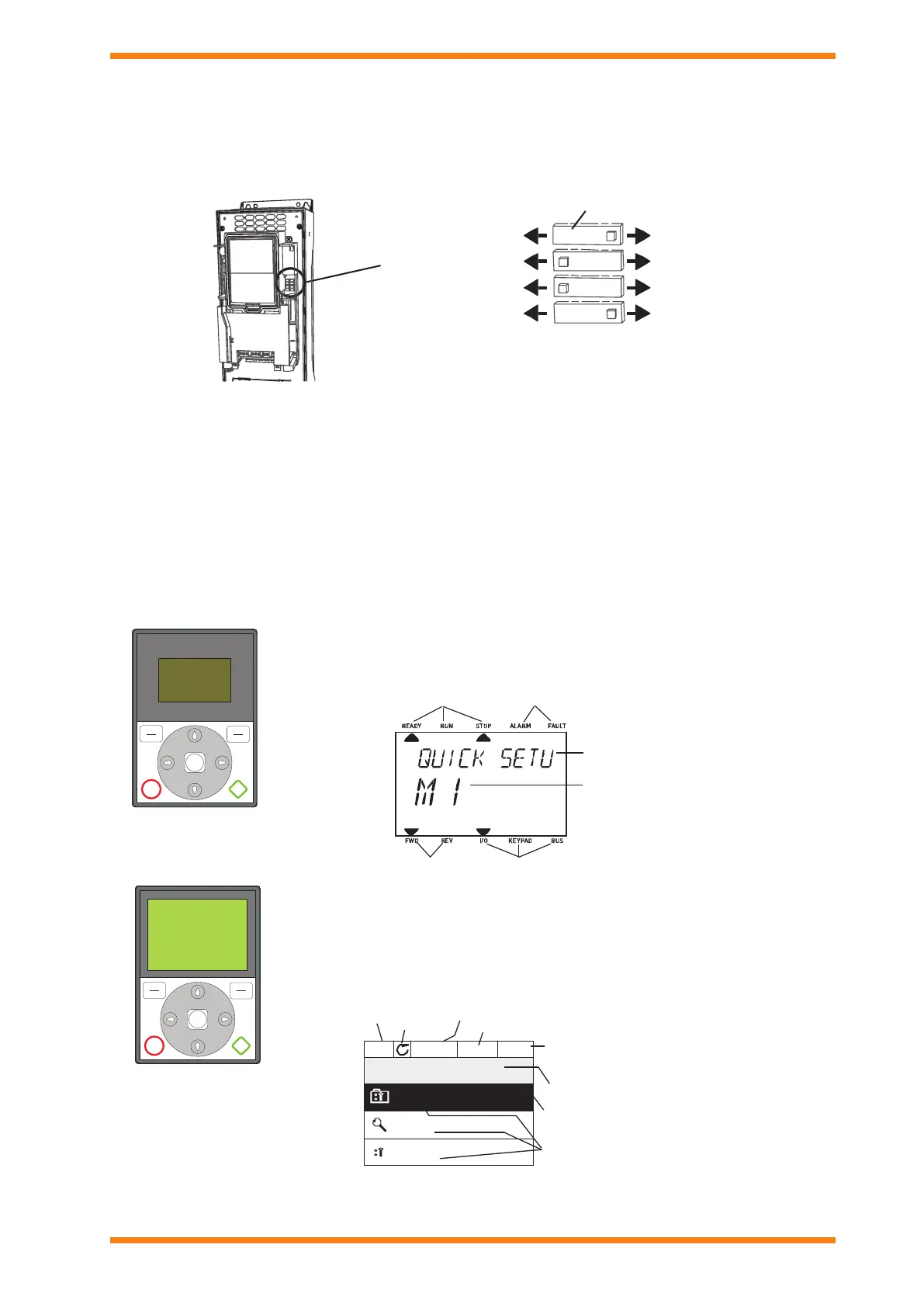
FWD REV I/O KEYPAD BUS
READY RUN STOP ALARM FAULT
The standard text keypad features an alphanumeric display with seven indicators for run status
(READY, RUN, STOP, ALARM, FAULT, FWD, REV), and three indicators for control source (I/O,
KEYPAD, BUS). There are also two text lines displaying description (of menu, value or fault) and
location (reference to menu and parameter) or value (numerical, textual values).
Indicators:
Status
Indicators:
Alarm, Fault
Indicators:
Direction
Indicators:
Controlplace
Groupor parame-
tername
Menu location
A replacement advanced commissioning keypad is available as an accessory (ACC/VSD2H
GRAPHIC DISPLAY). The commissioning keypad can also be used to store the parameter settings
and transport them to another drive (ref: M6.5). The top row is the drive status eld, and the second
row is the location eld describing the position in the selection menu. The remaing three rows
can be used for display of information. The commissioning keypad has extra features (help and
information displays, favourites, multi-monitor of 9 selected values).
text keypad
OK
STOP START
BACK
RESET
LOC
REM
commissioning keypad
(ACC/VSD2H GRAPHIC
DISPLAY accessory)
Main Menu
Quick Setup
(17)
Parameters
(12)
STOP READY I/O
ID:M1
(5)
Monito r
Location field
Status field
(ParameterID number
Main Menu
Quick Setup
(17)
Parameters
(12)
STOP READY I/O
ID:M1
(5)
Monito r
Activated group/item. Press OK to enter.
Number of itemsinthe group
STOP/RUN
Status field
READY/NOT READY/FAULT
Control place:
PC/IO/KEYPAD/FIELDBUS
ALARM
and current menu location)
Number of itemsinthe group
Direction
 Loading...