8
the front panel 'Input' switch. The outputs from each channel are low impedance and designed to
operate with long cable runs without signal degradation.
A standard IEC mains inlet is provided for AC mains power. Operating voltage of either 120 or 240
volts is selectable by rotating the fuse holder incorporated into the mains inlet socket
.
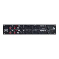
INPUT SECTION
The input section of the Series 80B rack is designed specifically for professional audio
applications. It consists of a very high quality transformer-coupled microphone amplifier and a
separate electronically balanced
levels is accommodated, adjustment of the gain is extremely smooth, particularly at high signal
a wide range of input levels with a frequency response that extends to
above 40kHz. Naturally, best results will be achieved using a high quality condenser microphone.
The microphone amplifier will however also bring out the best in either a dynamic or ribbon
microphone. The combination of high gain with low noise is particularly useful when working with
ribbon
Series 80B
Series 80B
®
®
®
line input amplifier.
The microphone amplifier is of a unique design that is able to handle signal levels from -60dBu to as
high as +15dBu without the use of a separate pad switch. Even though such a wide range of signal
levels where other designs tend to have cramped level adjustment at the end of the control.
In addition, it exhibits near theoretical minimum noise figures, has an extremely fast transient
response and accommodates
microphones as most models have an inherently low output level.
When connecting a microphone, set the 'Mic' gain control to its minimum position (fully anti-
clockwise) and the 'Output Level' control to its '0' position. The 'Input' switch should not be pressed
in. If required, engage the '+48V' phantom power whilst the 'Mic' gain control is at minimum. Allow up
to 30 seconds for the microphone to reach its normal operating level and advance the 'Mic' gain
control until a suitable level is achieved at the output of the unit. The 'O/P Peak' LED signal indicator
is located above and to the left of the output level control. It is designed to light when a signal level of
+10dB occurs at the output stage. This provides plenty of overload margin as the rack
unit is capable of very high output levels (up to +26dBm into a balanced load). By setting the level as
described above, adequate headroom is maintained and there should be no danger of overloading
following equipment.
The phase (polarity) reverse switch is employed when phase interference occurs between multiple
microphones. Such interference results when microphones, at various placements, pick up the
same sound source at slightly different times. When the output of the microphones combine,
cancellation occurs at certain frequencies. This effect is known as comb filtering. Switching the
polarity on one microphone may serve to minimise this effect.
To set up the for a line level signal, depress the 'Input' switch and adjust the 'Line' gain
control to its midway position, with the 'Output Level' control set to '0'. Avoid selecting the +48V
phantom power in the 'Line' mode, as this will cause a loud noise when the phase reverse switch is
operated. At its midway position in Line mode, the unit is designed to give unity, or '0dB' gain. This
makes for an easy reference point when using line level inputs and a detent is provided at the centre
point of the gain control for this purpose. As described above, the 'Output Level' control and LED
indicator is used to set an appropriate level through the unit.
 Loading...