3
4
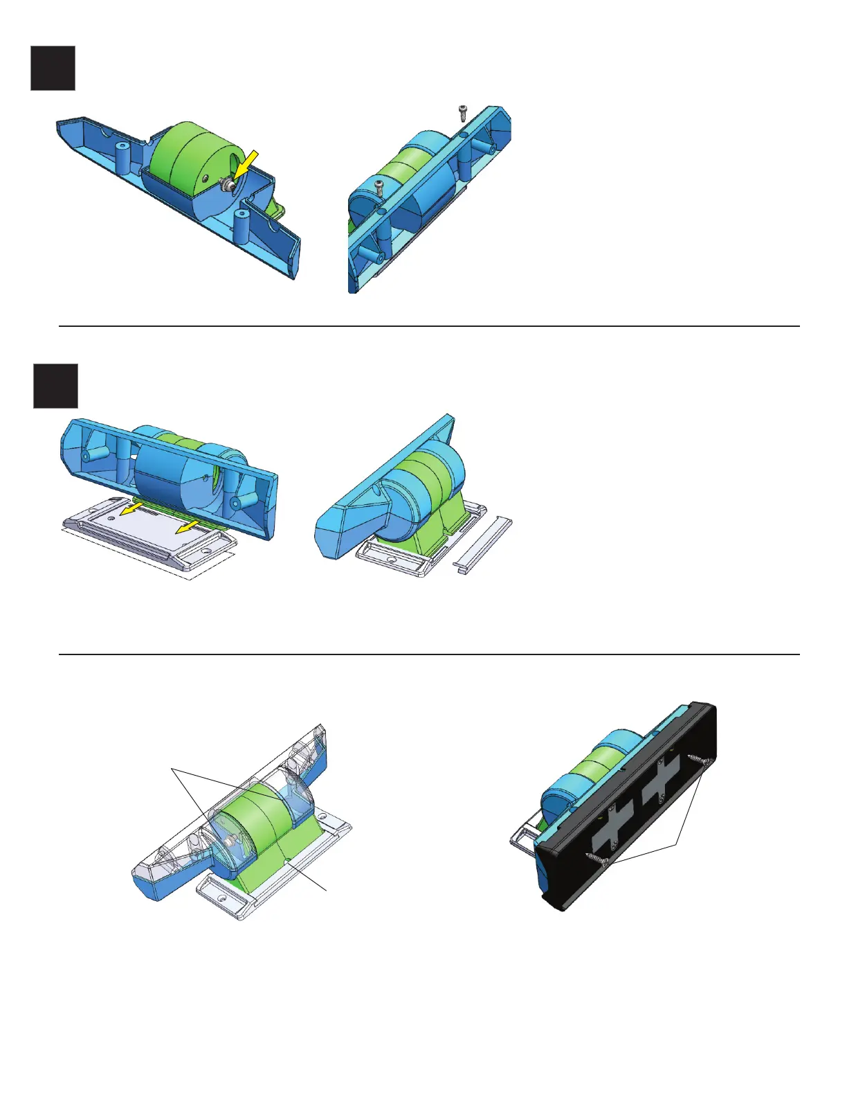
Install the 2 screws/washers for the pivot
loosely into the pivot hole as shown. Now install
the lower half of the main mount (C) being
careful to be sure the washers are in the correct
location.
Install the upper half of the main mount (D) in
place, be sure the pivot screws and washers are
in the correct position. Use two 2.8mm screws
as shown and tighten.
The mounting Foot is designed to use either
the included VHB tape or screws (not included)
to mount the Pedestal. It can be pre-mounted
before the main mount if the location is
difficult to reach with the complete assembly
or to allow easier access tho the mounting
screw locations. It also allows removal of the
main assembly without removing the screws
or VHB tape as needed.
Slide the Pedestal base assembly into the
mounting foot as shown then slide the rear
keeper in place to secure the main assembly.
Pedestal adjustment and pivot detail
Installation of Trigger Mounting Plate
(Use original Trigger 6 Shooter mount included in Trigger
controller kit. Not included in Pedestal Kit)
Pivot screw, one on
each side.
Allows adjustment of
tension on pivot.
NOTE: Be careful not to over tighten as the screws may strip and the pivot
will no longer operate as required.
E
D
C
F
Note 12 volt power wire exit
location if used.
Please contact AAC for help or warranty support at www.triggercontroller.com
3 mm Flat head
screws
VHB
 Loading...