4
Select Description
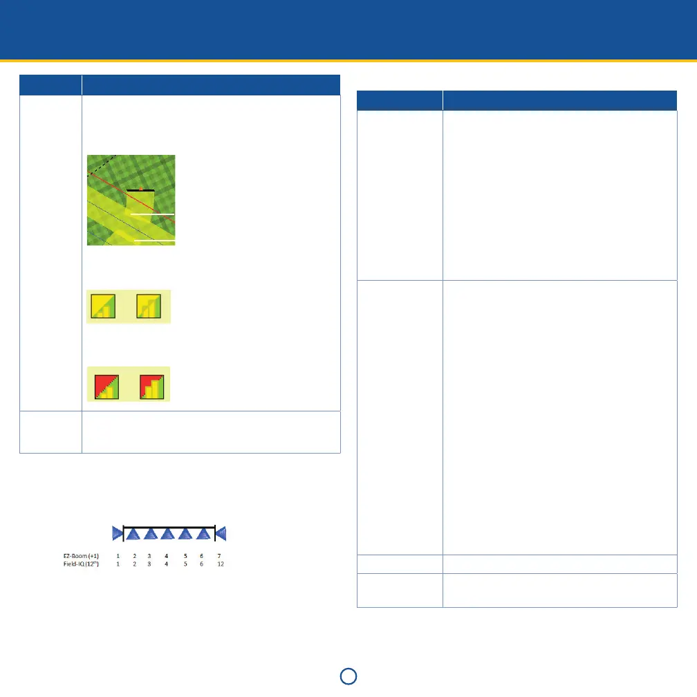
Overlap Start Overlap: The amount of intentional overlap when
going into a non-covered section of the field.
End Overlap: The amount of intentional overlap when
going into a previously covered area.
Start Overlap
End Overlap
Coverage Switching Overlap: The amount of side-to-side
coverage overlap before a section shuts down.
1%
99%
Boundary Switching Overlap: The amount of side-to-side
boundary overlap before a section shuts down.
1%
99%
Coverage
Allowable
Rate Error
Coverage allowable rate error.
c. If required, set Fence Nozzles. If Right or Both is selected, the
option for Right Nozzle Wiring appears. Select the wiring
configuration of your sprayer to ensure control of the correct
section for right fence nozzle:
7. Set up Rate Control.
a. If On, enter the number of drives for this location and select
the module serial number(s). If there is more than one module,
select the width associated with the module.
b. In Drive Setup, complete the Valve Setup. The options are:
Select Description
Valve Type • Servo: Standard 2-wire servo, performs more
slowly.
• Servo Fast: Fast 4-wire servo, performs more
quickly.
• PWM: 2-wire PWM valve, commonly used to
control hydraulic flow to the pump.
• Hardi % Bypass Servo: Used on Hardi sprayers
equipped with 3-way section valves that return
flow to the tank when the boom section is off.
• Pump Servo: Servo valve commonly used to
control hydraulic flow to the pump.
• Electric Over Hydraulic: A valve that uses electric
current to control the hydraulic valve output.
Plumbing Set the valve plumbing for servo-type valves only
(that is, Servo, Servo Fast, and Hardi % Bypass
Servo).
Note – Pump Servo does not have a plumbing type as it
controls hydraulic flow to the pump. This is similar to a
PWM setup.
The options are:
• Inline: The control valve is between the pump
and the sections/nozzles. This means that the
control valve controls the amount of material
out to the section/nozzles directly.
Note – To increase the amount of material that is sent
to the section/nozzles, the control valve must open
more in order to force more material to the sections/
nozzles.
• Bypass: The control valve is between the pump
and the tank. This means that the control valve
controls the amount of material that goes back
to the tank.
Note – To increase the amount of material that is sent
to the section/nozzles, the control valve must close
more in order to force more material to the sections/
nozzles.
Auxiliary Valve Disabled, Master, or Dump
Pump Disarming
Switch
Disabled or Enabled
 Loading...