2 Connecting to an EZ-Boom System
12 EZ-Guide 500 System Cabling Guide
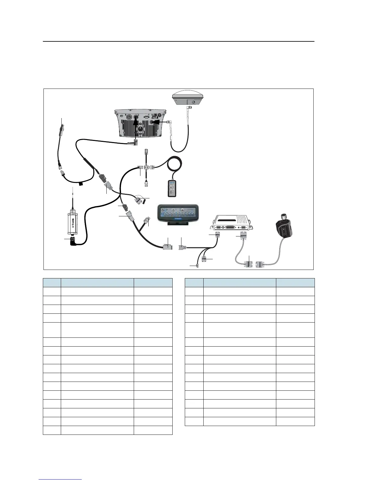
EZ-Steer 500 system / EZ-Boom system / 900 MHZ RTK radio
This figure shows how to connect the EZ-Steer 500 system to an EZ-Boom 2010 system
with a 900 MHz radio for RTK corrections:
Item Description Part number Item Description Part number
A GPS antenna 77038-00 1 “P4” connector –
B GPS antenna cable 50449 2 “P2” connector –
C Remote keypad (optional) 66030-00 3 “P1” connector –
D External interface cable 62749 4 “R2” connector –
E EZ-Boom controller – 5 Laptop connector (for
firmware upgrade)
–
F EZ-Steer controller – 6 Alternate power connector –
G EZ-Steer motor 53058-00 7 “S1“connector –
H EZ-Steer motor cable 62257 8 “P3“connector –
I EZ-Steer extension cable 62974 9 “P1“connector –
J EZ-Boom cable 61437 10 “S3“connector –
K EZ-Guide 500-to-radio cable 62082 11 “P2” connector –
L SiteNet™ radio – 12 “P3” connector –
M Radio antenna 22882-00 13 “S5” connector –
N Power cable 62817 14 “P1” connector –
O Power connector cable 62818 15 To power –
P EZ-Guide 500 lightbar 66100-xx
A
B
C
D
E
F
1
G
2
3
H
4
6
5
I
12
11
10
9
J
7
8
14
13
K
P
N
M
L
O
15