EZ-Guide 500 System Cabling Guide 67
Accessory Connections 8
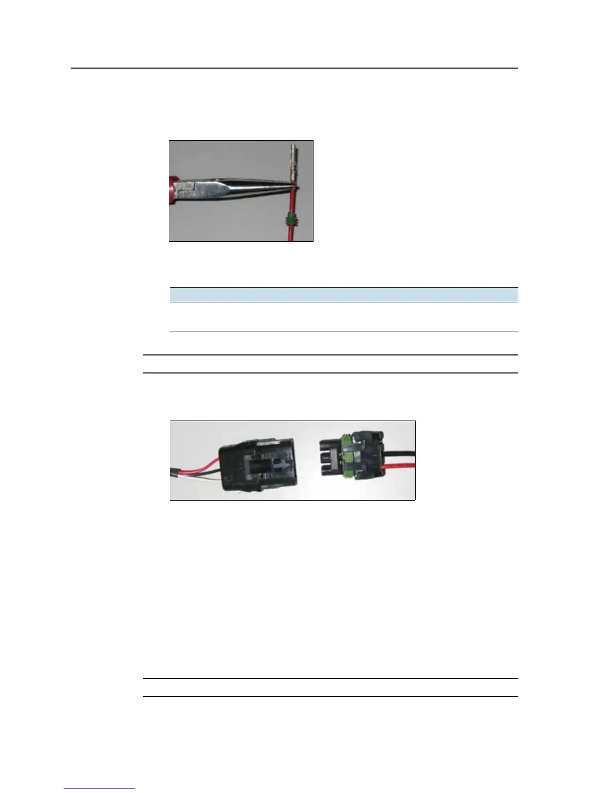
3. Crimp terminal connectors to the ends of the two wires with an appropriately-
sized crimp tool or pliers and then solder the terminal connectors to the wire to
ensure a secure connection:
4. Insert the wires with terminal connectors and the cable seals into the
appropriate holes on the female WeatherPack connector:
C
CAUTION – Ensure that you do not supply either wire with power. If necessary, use a relay.
5. Plug the female connector into the male connector on the lightbar's interface
cable:
Note – If you are also using radar, connect the radar cable to the WeatherPack connector
on the interface cable and then connect the switch cable to the spare WeatherPack
connector on the radar cable.
Step 3. Attaching the switch wires
Option 1: Connecting the switch wire to an implement or spray source
If you connect the switch wire to an implement or spray source, coverage is engaged
when you turn on the implement or spray source. This requires an automotive relay to
close the circuit when power is supplied.
C
CAUTION – Ensure that you do not supply either wire with power. If necessary, use a relay.
Switch wire Connector
Ground B
Switch C