8 Accessory Connections
68 EZ-Guide 500 System Cabling Guide
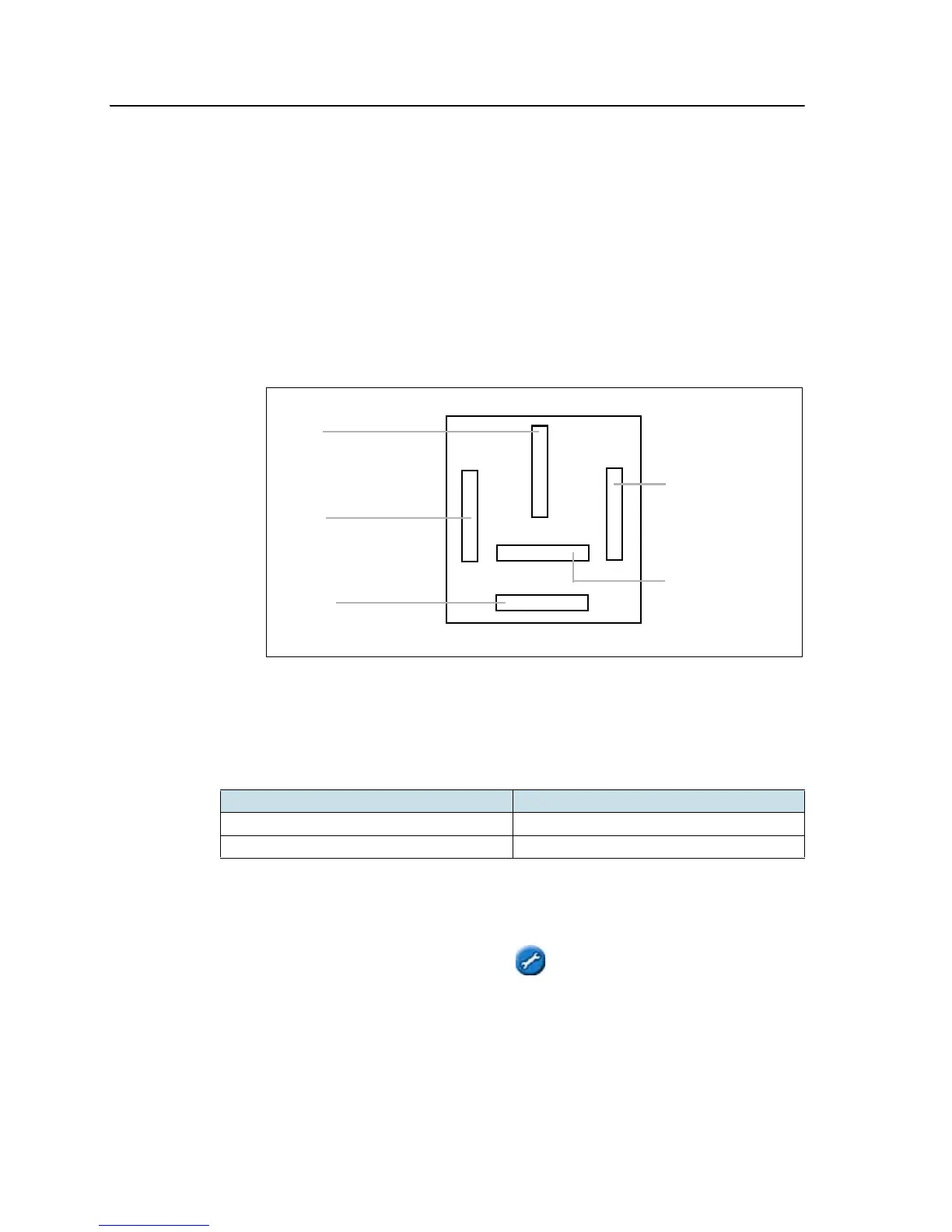
To connect the relay :
1. Connect the 3-pin WeatherPack end of the switch cable to the 3-pin
WeatherPack connector on interface cable.
2. Connect one of the switch wires to pin 87 on the relay.
3. Connect the other switch wire to pin 30 on the relay.
4. Connect a wire from a ground connection on the implement to pin 85 on the
relay.
5. Locate a point on the implement that outputs 12V only when the implement is
engaged. Connect a wire from that point to pin 86 on the relay.
Note – Leave pin 87a (in the middle of the relay) unconnected.
Option 2: Connecting the switch wire to an SPST toggle switch
You can connect an SPST toggle switch to manually turn coverage logging on or off:
Step 4. Enabling the switch on the lightbar
From the main guidance screen:
1. Press until you have selected the icon.
2. Press . The Configuration screen appears.
3. Ensure that the User Mode field is set to Advanced.
Switch state Result
On (switch is closed) Coverage logging is enabled
Off (switch is open) Coverage logging is disabled
Pin 86:
To 12 V (when
implement is
enabled)
Pin 87a:
Unused
Pin 30:
Connect one wire from
the WeatherPack
Pin 87a:
Connect the other wire
Pin 85:
Connect to vehicle
ground
from the Weatherpack