Date: April 14, 2020 Doc No: PS-M-0871 Ver: B Page 11 of 21
1) Aluminum Frame 2) M8 Stainless Bolt
3) Flat Stainless Washer 4) Spring Stainless Washer
5) HEX Stainless Nut
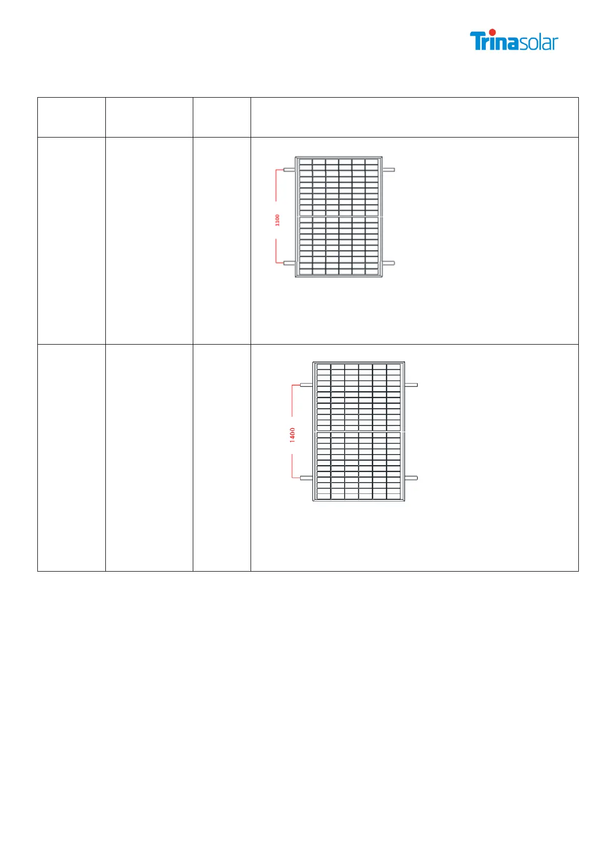
Mounting Direction(The crossbeam is perpendicular to the long side
frame)
120 pcs
Back
sheet-
Glass
Framed
Module
*NOTE: The above-described distance is from the middle of the bolts to the
middle of the bolts
*NOTE: Need two support rails below the PV module to make sure the
Mechanical load.
*NOTE: The actual load is + 5400Pa/-2400Pa
144 pcs
Back
sheet-
Glass
Framed
Module
*NOTE: The above-described distance is from the middle of the bolts to the
middle of the bolts
*NOTE: Need two support rails below the PV module to make sure the
Mechanical load.
*NOTE: The actual load is + 5400Pa/-2400Pa
B. Mounting with Clamps
Trina Solar has tested its modules with a number of clamps from different manufacturers,
mounting bolt of at least M8. The length of clamp ≥40mm (1.57in) , thickness≥ 3mm(0.12in).
The clamp must overlap the module frame by at least 7mm (0.28in) but no more than 11mm
(0.43 in).
Use at minimum 4 clamps to attach modules to the mounting rails.
Modules clamps should not come into contact with the front glass and must not deform the
frame.
Be sure to avoid shadowing effects from the module clamps.
The module frame is not to be modified under any circumstances.
When choosing this type of clamp-mounting method, use at least four clamps on each module,
two clamps should be attached on each long sides of the module (for portrait orientation).
Depending on local wind and snow loads, additional clamps may be required to ensure that