Date: April 14, 2020 Doc No: PS-M-0871 Ver: B Page 15 of 21
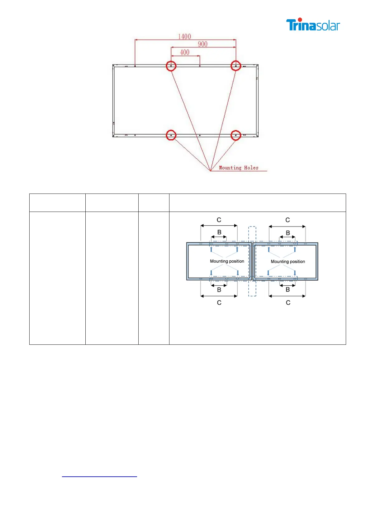
Figure: Mounting holes schematic of the single module for the 2V installation method
+700 Pa /-700
Pa(Special
Requirement,
need confirm
with Trina)
*NOTE: Installation hole marked 900 mm pitch is the
installation hole of this installation mode.
*NOTE: The above-described distance is from the middle
of the bolts to the middle of the bolts
The actual load is + 1050Pa/-1050Pa
7.2.2 GROUNDING
All module frames and mounting racks must be properly grounded in accordance with
appropriate respective National Electrical Code.
Proper grounding is achieved by bonding the module frame(s) and all metallic structural
members together continuously using a suitable grounding conductor. The grounding conductor
or strap may be copper, copper alloy, or any other material acceptable for use as an electrical
conductor per respective National Electrical Codes. The grounding conductor must then make a
connection to earth using a suitable earth ground electrode.
Trina Solar modules can be installed with the use of third party listed grounding devices for
grounding the metallic frames of PV modules. The devices have to be installed in accordance
with the grounding device manufacturer’s specified instructions.
Please refer to the “Product Catalogue” link for detailed grounding hole locations and size at
http://www.trinasolar.com/
Grounding hardware comes in a package that includes the grounding screw, flat washer、star