Date: April 14, 2020 Doc No: PS-M-0871 Ver: B Page 18 of 21
calculated at the lowest expected ambient temperature for the location. This can be done using
the following formula.
Max System voltage ≥ N * Voc * [1 + TCvoc x (Tmin-25)]
Where
N Number of modules in series
Voc Open circuit voltage of each module (refer to product label or data sheet)
TCvoc Thermal coefficient of open circuit voltage for the module (refer to data sheet)
Tmin The lowest expected operating temperature of module
Each module has two standards 90°C sunlight resistant output cables each terminated with
plug & play connectors. The PV Wire cables are 12AWG in size. This cable is suitable for
applications where wiring is exposed to the direct sunlight. We require that all wiring and
electrical connections comply with the appropriate National Electrical Code.
The minimum and maximum outer diameters of the cable are 5 to 7mm (0. 038 to 0.076in2).
For field connections, use at least 4mm2 copper wires insulated for a minimum of 90°C and
sunlight resistance with insulation designated as PV Wire.
The minimum bending radius cables should be 43mm (1.69in).
7.2.3.1 WIRING
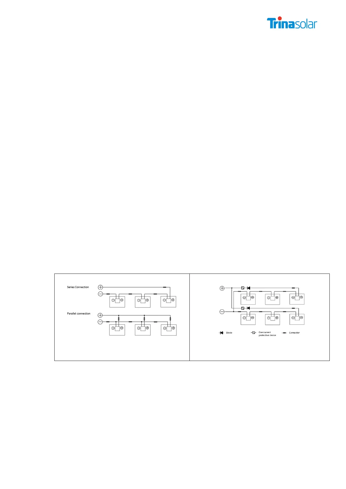
To ensure proper system operation the correct cable connection polarity (Figures 1 & 2) should
be observed when connecting the modules to each other or to a load, such as inverter, a
battery etc. If modules were not connected correctly, the bypass diode could be destroyed. PV
modules can be wired in series to increase voltage. A series connection is made when the wire
from the positive terminal of one module is connected to the negative terminal of the next
module. Figure 1 shows modules connected in series. PV modules can be connected in parallel
to increase current (Figure 2). A parallel connection is made when the wire from the positive
terminal of one module is connected to the positive terminal on the next module.
The number of modules in series and in parallel shall be designed reasonably according to the
system configuration.
All instructions above have to be obeyed to maintain Trina Solar’s limited warranty.
Connecting in parallel after connected in series
7.2.3.2 FUSING
When fuses are fitted they should be rated for the maximum DC voltage and connected in each,
non-grounded pole of the array (i.e. if the system is not grounded then fuses should be
connected in both the positive and negative poles).
The maximum rating of a fuse connected in series with an array string is typically 20A but the
actual module specific rating can be found on the product label and in the product datasheet.
This fuse rating value also corresponds to the maximum reverse current that a module can
withstand (when one string is shaded then the other parallel strings of modules will be loaded
by the shaded string and current will flow) and therefore impacts the number of strings in
parallel.