Page 29
E Series Ethernet Radio – User Manual
Version 08-10
Part E – Getting Started - ER45e
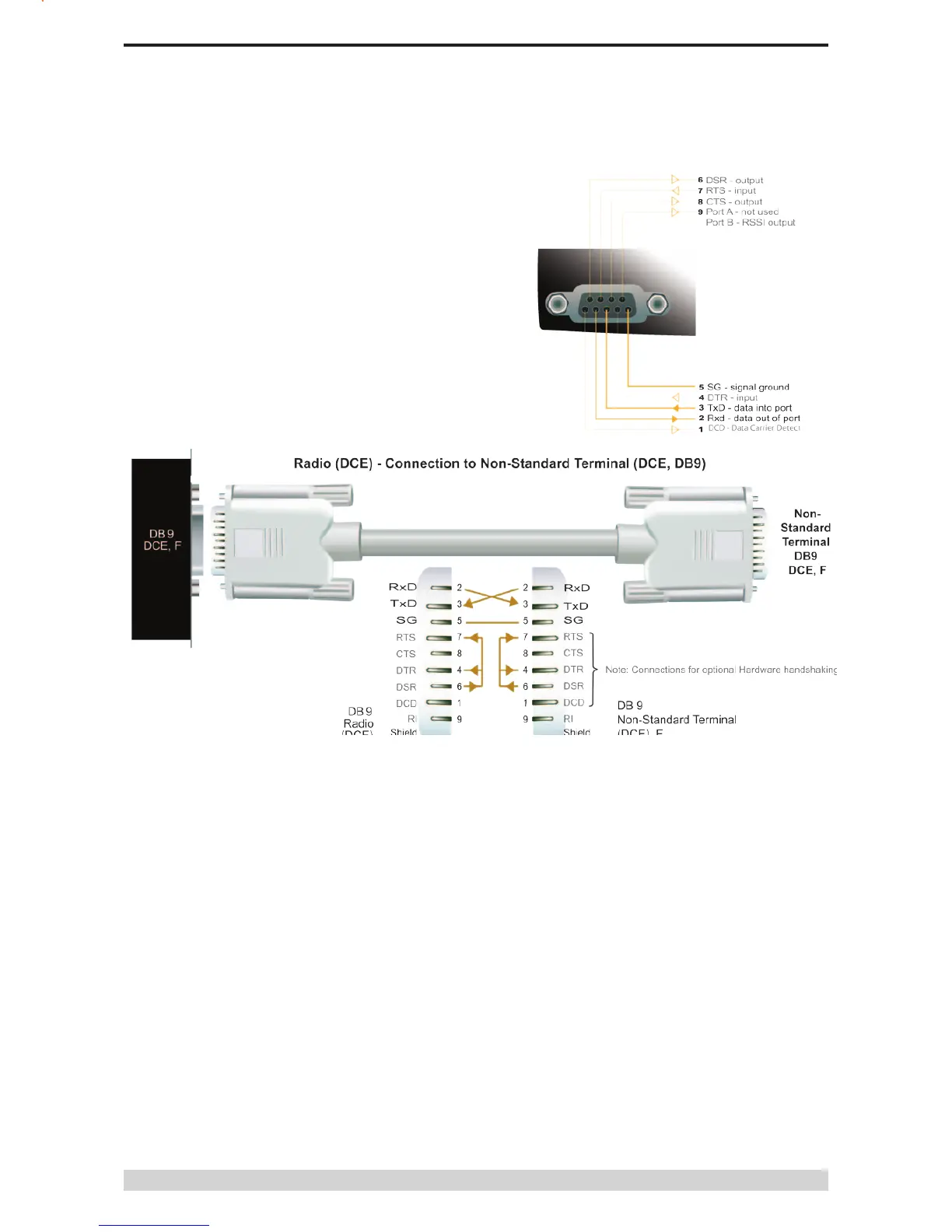
Data Port
The Data Port is wired as a RS232 DCE, congurable for no
handshaking (3-wire) interface, or for hardware or software (X-on/
X-off) ow control. In most systems ow control is not required, in
which case only 3 wires need to be connected between the radio
and the application device.
Typical pins used:
• Pin 2 (RxD) - data output from the radio modem,
• Pin 3 (TxD) - data input to the radio modem,
• Pin 5 (SG) - signal ground.
See Part D – System Planning and Design - Data Connectivity, for
further details of other cable congurations.
RS232 Connector Pin outs (DCE)
Data Port, Female DB9